
Non-catalytic permeable membrane reactor for producing hydrogen from ammonia-containing tail gas in MOCVD process and application

A membrane reactor, non-catalytic technology, applied in hydrogen production, chemical instruments and methods, specific gas purification/separation, etc., can solve the problems of increased energy consumption, poor selectivity of hydrogen production, high partial pressure, etc., to reduce load and Cost, reduction of exhaust emissions, and significant economic benefits

Pending Publication Date: 2020-05-08
ZHEJIANG TIANCAIYUNJI TECH CO LTD
View PDF2 Cites 1 Cited by
  • Summary
  • Abstract
  • Description
  • Claims
  • Application Information

AI Technical Summary

Problems solved by technology

[0005] However, the catalysts and fixed-bed shell-and-tube reactors used in the traditional catalytic thermal cracking of ammonia for hydrogen production face the following problems: First, the raw materials of ammonia gas or liquid ammonia used are basically pure ammonia. In addition to ammonia, there are also a large amount of nitrogen and hydrogen, and the corresponding concentration or partial pressure of NH3 is low and the partial pressure of nitrogen and hydrogen is high. Therefore, the traditional ammonia decomposition catalyst is directly used to convert the catalytic decomposition of ammonia to hydrogen production from MOCVD epitaxy tail gas The efficiency is very low, the selectivity of hydrogen production is also relatively poor, the processing capacity of the catalyst or the space velocity of the decomposition reaction cannot reach the production scale and technical indicators of pure ammonia decomposition hydrogen production; second, the traditional ammonia catalytic thermal cracking hydrogen production reaction The selected catalyst and the fixed bed tube reactor, the raw material gas and the reaction gas need to be circulated during the reaction process, so that the ammonia can be completely decomposed, the energy consumption will increase, and the hydrogen in the reaction system cannot be removed in time and the hydrogen in the cycle The accumulation of concentration causes the partial pressure of hydrogen to increase continuously, which further inhibits the decomposition of ammonia; thirdly, in the mixed gas generated by the reaction, in order to avoid the amount of circulation, it is necessary to remove the reactor in time after the reaction reaches a certain period of time, and then react There is still a large amount of nitrogen and a small amount of undecomposed ammonia in the gas, which increases the load and cost of subsequent PSA hydrogen extraction; fourth, the traditional pure ammonia decomposition hydrogen production process mostly obtains higher yields at higher temperatures. For conversion rate and hydrogen production rate, the general reaction temperature is 600-800°C, and the relative energy consumption is relatively high. Therefore, for MOCVD epitaxial tail gas with low ammonia concentration and high hydrogen concentration, catalytic heat should be carried out at a lower temperature. It is very difficult for the cracking reaction to make the ammonia conversion rate and hydrogen selectivity high, or the space velocity on the unit catalyst at least reach the processing scale and technical indicators of pure ammonia decomposition hydrogen production; fifth, if the ammonia in the MOCVD epitaxy tail gas is decomposed The conversion rate is low, or the obtained hydrogen cannot be removed in time, so that the content of undecomposed ammonia in the reaction gas is too high, resulting in the increase of the cost of tail gas separation and hydrogen extraction or hydrogen reuse. Purification and removal, poor technical and economic benefits

Method used


Image

  • Non-catalytic permeable membrane reactor for producing hydrogen from ammonia-containing tail gas in MOCVD process and application
  • Non-catalytic permeable membrane reactor for producing hydrogen from ammonia-containing tail gas in MOCVD process and application
  • Non-catalytic permeable membrane reactor for producing hydrogen from ammonia-containing tail gas in MOCVD process and application

Examples


Embodiment 1

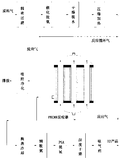
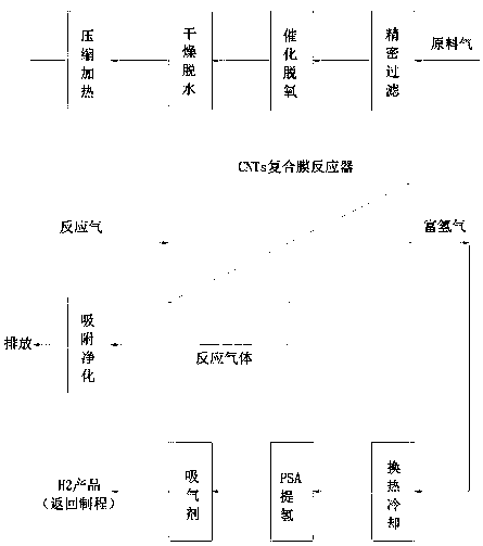
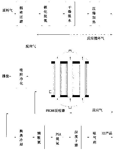
[0031] Such as figure 1 As shown, a non-catalytic permeable membrane reactor for hydrogen production from tail gas containing ammonia in MOCVD process and its application, which contains active components cobalt 15~20% (w / w, the same below), molybdenum 14~16%, containing Catalyst particles composed of 4-6% lanthanum as a promoter component, 3-5% potassium as a promoter, and 53-64% pretreated carbon nanotubes (CNTs), loaded on alumina as a support In the inorganic ceramic membrane tube coated with a metal palladium membrane layer, the thickness of the membrane layer is 1 micron, forming a non-catalytic permeable membrane reactor (PBCMR, Packed Bed Catalytic Membrane Reactor) with a fixed bed of catalyst filled in the membrane tube, according to The following steps carry out the catalytic thermal cracking hydrogen production reaction of ammonia,

[0032] (1) The raw material gas is from the production of LED-GaN epitaxial wafers, and its MOCVD epitaxial tail gas is mainly compo...

Embodiment 2

[0035] The pretreatment of the multilayer carbon nanotube CNTs described in Example 1 is to add about 1 to 2 g of commercially sold CNTs carriers with a specification of 10 nm into a total volume of about 230 to 260 mL of nitric acid with a mass concentration of 30% and about 70% In the mixed solution of nitric acid with mass concentration, heat to 110~120°C, stir evenly, and azeotropically reflux at 110~120°C for 6~8 hours, cool to ambient temperature, vacuum filter, wash with deionized water for two After three times until neutral, the resulting filter cake is dried at 120°C for 1-2 hours, ground into 10-20nm powder, mixed with 1-1.5g of MgO powder, roasted and cooled under nitrogen flow at 630-660°C A mixed carrier of CNTs and MgO is formed for loading active components Co, Mo, cocatalyst La, and promoter K.

Embodiment 3

[0037] On the basis of Examples 1 and 2, the catalyst for hydrogen production by thermal cracking of tail gas containing ammonia in the MOCVD process was prepared by alcohol thermal method, and 2~4g of pretreated multilayer carbon nanotubes (CNTs) and magnesium oxide (MgO) were mixed with the carrier , added to about 50~60mL absolute ethanol solution, heated to 30~50°C and stirred to form a slurry, then added a cobalt-molybdenum bimetallic catalyst with a total volume of about 50~100mL to prepare the precursor as cobalt nitrate (Co( NO3)2) and molybdenum nitrate (Mo(NO3)3) mixed solution, the co-catalyst precursor is a mixed solution of lanthanum nitrate (La(NO3)3) and potassium nitrate (KNO3), and ethanol solution, then stir and mix evenly, and then Add about 10~30mL of ammonia water, adjust the pH of the mixed solution until it is greater than 10, then heat and stir to form a slurry again, and perform ultrasonication on the slurry for 0.5~1h and dry at 100~130°C for 2~4 hours...


PUM


Abstract

The invention discloses a non-catalytic permeable membrane reactor for producing hydrogen from ammonia-containing tail gas in an MOCVD process and application. The catalyst is catalyst granules whichcomprise10-30% (w / w) of an active component cobalt, 5-20% (w / w) of an active component molybdenum, 1-10% (w / w) of a co-catalytic component lanthanum, 1-5% (w / w) of an accelerant potassium, and 35-83%(w / w) of pretreated carbon nanotubes (CNTs), wherein the catalyst granules are loaded in a ceramic membrane tube employing aluminum oxide as a supporting body and being coated with a metal palladium membrane layer, thereby forming a packed bed catalytic membrane reactor (PBCMR) packed in a catalyst fixed bed layer in the membrane tube; ammonia-containing tail gas in the MOCVD process is pretreatedand then enters a membrane reactor; at the reaction temperature of 400 to 600 DEG C, ammonia thermal cracking catalytic reaction is carried out under the reaction pressure of 1.0-3.0 MPa, wherein thereaction gas is subjected to adsorption refining deamination, pressure swing adsorption purification and metal getter purification to obtain a hydrogen product with the purity larger than 6-7 N; thehydrogen product then is returned to the MOCVD process to be recycled. By means of the technology, the blank of LED industry green and circular economy development is filled.

Description

technical field [0001] The invention belongs to the technical field of hydrogen preparation for comprehensive utilization of ammonia-containing (NH3) waste gas in the manufacturing process of semiconductor light-emitting diodes (LEDs), and in particular relates to a non-catalytic method for hydrogen production from MOCVD (metal oxide chemical vapor deposition) ammonia-containing tail gas Permeable membrane reactor and its application. Background technique [0002] MOCVD (Metal Oxide Chemical Vapor Deposition) process (equipment) is a modern method and means for the research and production of compound semiconductor materials, especially as a method and equipment for the industrial production of new light-emitting materials-light-emitting diodes (LEDs). The main methods and means of optoelectronic devices and microwave device materials, in addition to LEDs, also include lasers, detectors, high-efficiency solar cells, photocathode, etc., which are indispensable methods and equi...

Claims


Application Information

Patent Timeline
Patent Type & Authority Applications(China)
IPC IPC(8): C01B3/04C01B3/50C01B3/56
CPCC01B3/047C01B3/56C01B3/505C01B3/508C01B2203/0277C01B2210/0012C01B2210/002C01B2210/0021C01B2210/0065Y02E60/36
Inventor 汪兰海钟娅玲陈运唐金财钟雨明蔡跃明
Owner ZHEJIANG TIANCAIYUNJI TECH CO LTD
Learn More