
Bone replacement materials

a bone and bone technology, applied in the field of bone and bone replacement materials, can solve the problems of pain and joint stiffness, lack of bone replacement material that is appropriate for restoring lost structure and function, and complex and delicate structure of natural synovial joints capable of functioning under critical conditions, and achieve the effect of facilitating cell growth and/or adhesion

Active Publication Date: 2016-05-03
WASHINGTON STATE UNIVERSITY
View PDF37 Cites 9 Cited by
  • Summary
  • Abstract
  • Description
  • Claims
  • Application Information

AI Technical Summary

Benefits of technology

The approach results in implants with mechanical properties closer to natural bone, reducing stress shielding, improving bone integration, and extending the lifespan of load-bearing implants by enhancing cellular adhesion and growth, thus addressing the limitations of existing materials.

Problems solved by technology

Yet, in spite of the enormous magnitude of this problem, there is still a lack of bone replacement material that is appropriate for restoring lost structure and function, particularly for load bearing applications.
This problem has resulted in a need for improved and mature biomaterials for load-bearing implants.
Natural synovial joints (e.g., hip, knee or shoulder joints) are complex and delicate structures capable of functioning under critical conditions.
Unfortunately, human joints are prone to degenerative and inflammatory diseases that result in pain and joint stiffness.
Premature joint degeneration may arise from deficiencies in joint biomaterial properties, from excessive loading conditions, or from failure of normal repair processes.
This resorption / bone loss effect will cause micromotion of the screws / implants in response to external loads and could further damage the interfacing bone layer and anchorage performances subsequent to possible loosening of the screw / implant (Gefen '02).
Early loosening of the screws / implants can not only delay or damage the healing process, but can also endanger adjacent anatomical structures and can even require surgery for the immediate removal of the failed implants (Lowery '98).
Such aspects inevitably impose a prolonged and painful rehabilitation process on patients, as well as substantial treatment costs.
Though cp-Ti exhibited better corrosion resistance and tissue tolerance as compared to stainless steel, cp-Ti's rather limited strength confined its applicability to specific parts such as hip cup shells, dental crown and bridges, endosseous dental implants, pacemaker cases and heart valve cages (Wang '96; Lee '02).
However, while the use of titanium-based alloys has been quite beneficial for such implants, high stiffness and high density of the alloy compared to natural bone is still a problem causing ‘stress-shielding.’ To improve the strength for load bearing applications such as total joint replacements, the alloy Ti-6Al-4V ELI (i.e., with extra low interstitial impurity content) was chosen as a candidate biomaterial for surgical implants in the late 1970's.
Despite the great progress that has been achieved in orthopedic biomaterials, fixation of implants to the bone host remains a problem.
Although ceramics portray excellent corrosion resistance, they cannot be employed as load bearing implants due to their inherent brittleness.
Similarly, porous polymeric systems cannot sustain the mechanical forces present in joint replacement surgery.
However, these methods present poor coating-substrate adherence and lack of uniformity of the coating in terms of morphology and crystallinity (Brossa, '93).

Method used


Image

  • Bone replacement materials
  • Bone replacement materials
  • Bone replacement materials

Examples


example 1

Laser Engineered Net Shaping (LENS™) and Developing Macro-Porous Structures

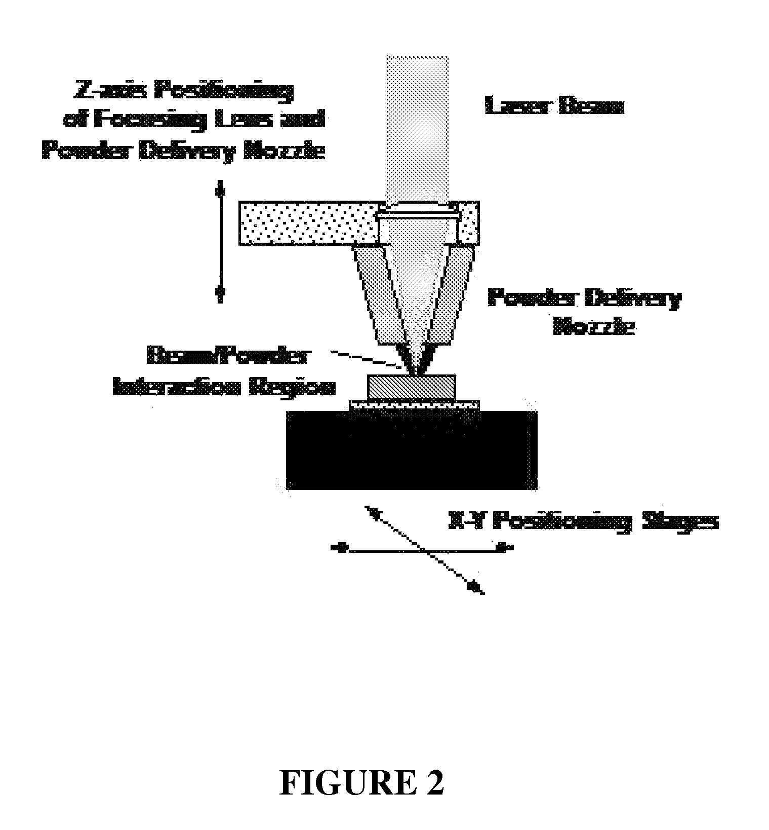
[0061]Unlike many existing rapid prototyping (RP) methods, the LENS™ technology uses metal powders to create functional parts that can be used in numerous applications. A schematic representation of an exemplary LENS™ process for providing the inventive implants is depicted in FIG. 2. Briefly, a LENS 750 machine uses 500 W of Nd:YAG laser power focused onto a metal substrate to create a molten puddle on the substrate surface. Metal powder is then injected into the molten puddle to increase the material volume. The substrate is then scanned relative to the deposition apparatus to write lines of the metal with a finite width and thickness. Rastering of the part back and forth to create a pattern and fill where material is required allows a layer of material to be deposited. Finally, this procedure is repeated many times until the entire object represented in the three-dimensional CAD model is produced on the ma...

example 2

Cell Growth on LENS Fabricated Macro-Porous Structures

[0067]Cell-materials interactions were studied between cp-Ti powder processed LENS parts and OPC1 human osteoblast cells (Winn '99). Cells were plated at a density of 105 cm2 in 100 mm tissue culture plates and cultured in McCoy's 5A medium (with L-glutamine, without phenol red and sodium bicarbonate). 5% fetal calf serum (FCS) and 5% bovine calf serum (BCS), 2.2 gm / liter sodium carbonate, 100 mg / liter streptomycin, 8 g / ml Fungizone (Gibco™ Labortories, Grand Island, N.Y.) were added in the media. LENS processed cp-Ti samples were autoclaved at 121° C. for 45 minutes.

[0068]FIG. 7 shows a SEM micrograph of OPC1 on the processed cp-Ti after 3 days in culture. It can be seen that cells attach tightly on the surface and numerous filopodia-like extensions exist between cell and surface. This result indicates that exemplary inventive LENS-processed parts are non-toxic and biocompatible.

example 3

Processing of Nano-Porous TiO2 on Ti and Cell-Materials Interaction

[0069]For nano-porous TiO2 materials, commercially pure (99.8% pure) titanium foils of 0.5 mm thickness from Supra Alloys (CA, USA) were used, which was cut into circular pieces of 12 mm diameter. Circular discs were abraded in silicon carbide paper successive grades from 600 to 1200 grit and then cleaned with distilled water in ultrasonic bath. Final polishing was performed in 1 μm alumina powder suspension. Polished titanium foils were ultrasonically rinsed in distilled water followed by isopropyl alcohol prior to anodization. For anodization, a two-electrode electrochemical anodization cell, with a platinum cathode and Ti anode, was used to fabricate the TiO2 nanotube at a constant dc voltage of 20V. Electrolyte solution was made by dissolving sodium fluoride, citric acid, 1(M) sulfuric acid in a ratio so that the final electrolyte components had F−: 0.1 mol / L, SO42−:1.0 mol / L and citric acid: 0.2 mol / L. The elect...


PUM

PropertyMeasurementUnit
diameteraaaaaaaaaa
diameteraaaaaaaaaa
pore sizesaaaaaaaaaa

Abstract

Provided are devices for bone tissue engineering, comprising a metal or metal-based composite member comprising an interior macroporous structure with porosity varying from 0-90% (v), the member comprising a surface region having a surface pore size, porosity, and composition designed to encourage cell growth and adhesion thereon, to provide a device engineered for a particular recipient subject. Engineered devices may further comprises a gradient of pore size, porosity, and material composition extending from the surface region throughout the interior of the device, wherein the gradient transition is continuous, discontinuous or seamless to promote cell in-growth. Additional aspects provide methods for bone tissue engineering, comprising use of a metal or metal-based composite member comprising an interior porous structure, wherein the pore size, porosity and material composition is selected to provide a device having an optimal density and / or elastic modulus and / or compression strength for a specific recipient. Fabrication methods are provided.

Description

CROSS-REFERENCE TO RELATED APPLICATIONS[0001]This application claims the benefit of priority to U.S. Provisional Patent Application Ser. No. 60 / 773,079, filed 14 Feb. 2006 and entitled “BONE REPLACEMENT MATERIALS,” which in incorporated herein by reference in its entirety.STATEMENT REGARDING FEDERALLY-SPONSORED RESEARCH[0002]The invention was made with government support under the Office of Naval Research DURIP grant number 11F-3825-5131 and the Office of Naval Research grant numbers 3812-1001 and 3812-1003 (N00014-1-04-0644 and N00014-1-05-0583). The United States government therefore has certain rights in the invention.FIELD OF THE INVENTION[0003]The invention described herein relates generally to bone and bone replacement materials, and more particularly to novel compositions and methods for the production of bone replacement materials having, inter alia, lower density and stiffness than prior art materials, and surface properties that enhance cellular adhesion and promote growth...

Claims


Application Information

Patent Timeline
Patent Type & Authority Patents(United States)
IPC IPC(8): A61F2/28B22F3/105A61L27/42A61L27/56B22F3/11A61F2/30A61F2/36
CPCA61L27/56A61F2/28A61L27/42B22F3/105B22F3/1109B22F3/1146A61F2310/00293A61L2430/02B22F2998/00A61F2/3094A61F2/30942A61F2/36A61F2/367A61F2/3676A61F2002/2817A61F2002/30004A61F2002/30006A61F2002/30011A61F2002/30013A61F2002/30028A61F2002/30029A61F2002/3093A61F2002/3097A61F2002/30115A61F2002/30118A61F2002/30179A61F2002/30224A61F2002/30235A61F2002/30322A61F2002/30593A61F2002/30616A61F2002/30677A61F2002/30838A61F2002/30909A61F2002/3692A61F2230/0006A61F2230/0058A61F2230/0069A61F2250/0014A61F2250/0023A61F2250/0026A61F2310/00017A61F2310/00023A61F2310/00029A61F2310/00047A61F2310/00053A61F2310/00113A61F2310/00155A61F2310/00179A61F2310/00185A61F2310/00227B22F3/1125B22F2207/17B23K2103/14B23K2103/16Y02P10/25B22F10/25B22F10/366B33Y70/10B33Y10/00B33Y50/00B33Y80/00B23K26/342B23K26/70A61L27/06A61L27/427A61L27/54A61L2300/404A61L2300/406A61L2300/414B23K26/0006
Inventor BANDYOPADHYAY, AMITBOSE, SUSMITA
Owner WASHINGTON STATE UNIVERSITY
Learn More