
Free-flowing sulfur transport, storage and use to produce energy, fertilizer or hydrogen without carbon dioxide

a free-flowing, sulfur-containing technology, applied in the direction of conveyors, sulfur preparation/purification, sustainable manufacturing/processing, etc., can solve the problems of high maintenance, excessive power consumption, sulfur precipitation from solution, etc., to reduce the tendency to corrode ferrous metal, and low solubility. the effect of the rate of chang

Inactive Publication Date: 2006-08-29
STECHER PTY INTERESTS L L C
View PDF18 Cites 11 Cited by
  • Summary
  • Abstract
  • Description
  • Claims
  • Application Information

AI Technical Summary

Benefits of technology

[0025]Among the many applications and implementations of this discovery are the simultaneous supply of sulfur and ammonia or sulfur and sulfur dioxide to locations where either or both are used either commercially or industrially, for example as fertilizers or raw materials, and the transport of sulfur from remote sources to oxidation operations for use as fuel, such as for example power plants that serve population centers with a high energy demand. The discovery also facilitates the transport of sulfur to production facilities for phosphoric acid and phosphates, and to any facility in general that utilizes sulfur, while minimizing the generation of sulfur dust, dust explosions or fires, bacterial degradation, moisture exposure, acid contamination, corrosion, and cartage. This invention also finds utility in hydrogen sulfide abatement processes in which the recovery of hydrogen as H2 gas is, or can be, accompanied by the generation of SO2, which can only be removed by reaction with further H2S to form elemental sulfur and water, thereby converting the hydrogen value in H2S to water rather than recovering it as molecular H2.

Problems solved by technology

While industrial chemicals and commodities can be transported long distances by pipeline, in many cases more economically than by rail or other forms of shipment, pipeline transfer has not been used for sulfur or for only short distances at most.
This is due to the high melting point of sulfur, the corrosiveness of sulfur when dissolved in typical solvents or when in contact with air or moisture, and the tendency of sulfur to precipitate from solution.
When shipped as a solution or slurry, sulfur tends to deposit on the pipeline walls, resulting in plating, plugging, and line blocking, all of which lead to unreliability, high maintenance, and excessive power consumption.
Methods for heating pipelines are complex and expensive.
High energy prices have since caused curtailment or abandonment of many Frasch operations and many large mineral reserves of native elemental sulfur remain undeveloped.
The storage and disposal of sulfur pose challenges as well, particularly those arising from environmental concerns.
Disposal in an environmentally sound yet economical manner is difficult to achieve.
Phosphate operations are typically very distant from sulfur production facilities, and many phosphate operations have been curtailed or shut down due to high energy prices or to supply disruptions caused by a lack of new power generating capacity despite increasing demand.
Shipping by unit train requires multiple locomotives, high-performance rail cars, and heavy-duty trackage, and is inherently inefficient due to the need to return empty rail cars to the sulfur source.
A major proportion of the ammonia production capacity in North America is currently shut down due to high the cost of natural gas as a raw material and to low product prices.
Sulfur dioxide is in large demand as a raw material for the manufacture of sulfuric acid, but a limiting factor is the high expense of transporting sulfur dioxide, as explained in the monograph by Rieber, M., Smelter Emissions Controls: The Impact on Mining and the Market for Acid, prepared for U.S. Department of the Interior Bureau of Mines, March, 1982, as quoted in U.S. Congress, Office of Technology Assessment, Copper: Technology and Competitiveness OTA-E-367 (Washington, D.C.: U.S. Government printing Office, September 1988, page 165, Box 8-A): “Liquid SO2 has a very limited demand in the United States, but, owing to its relatively high price per unit weight, it can be shipped long distances.
It is still extremely expensive to transport, however, because it requires special pressurized tank cars that usually return empty.
The market is too small to justify cost saving measures such as unit trains or special ocean tankers.”
Fouling and impairment of wells and pipelines by premature sulfur deposits is common and results in expensive maintenance problems and capacity losses due to shut-downs and extended off-line periods required for inspection, cleaning or replacement.
All the hydrogen value of hydrogen sulfide is thus lost to wastewater and low quality steam.
Natural gas is in short supply, however, and shortages and high prices are likely to persist for the foreseeable future.
Some of the carbon dioxide can be consumed as a raw material to make urea, but the economic value that is gained from the use of carbon dioxide in this manner is insufficient to compensate economically for the loss of methane, since CO2 is readily available from other sources in ways that do not involve methane consumption.
Unfortunately, however, the inefficiencies and high transportation costs of sulfuric acid make this impractical at remote hydrogen sulfide sources such as the Wyoming or Alberta sour gas fields.
The disposition of surplus acid at remote locations raises environmental concerns, since acidulation of carbonaceous ore bodies such as limestone presents a variety of problems including excess CO2 emissions.
This reduces the amount of economic value that can be extracted from the hydrogen sulfide.

Method used


Image

  • Free-flowing sulfur transport, storage and use to produce energy, fertilizer or hydrogen without carbon dioxide
  • Free-flowing sulfur transport, storage and use to produce energy, fertilizer or hydrogen without carbon dioxide
  • Free-flowing sulfur transport, storage and use to produce energy, fertilizer or hydrogen without carbon dioxide

Examples


example 1

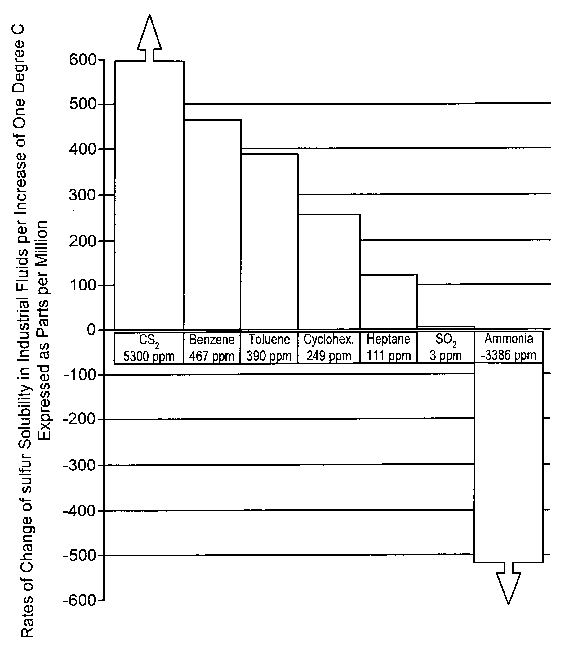
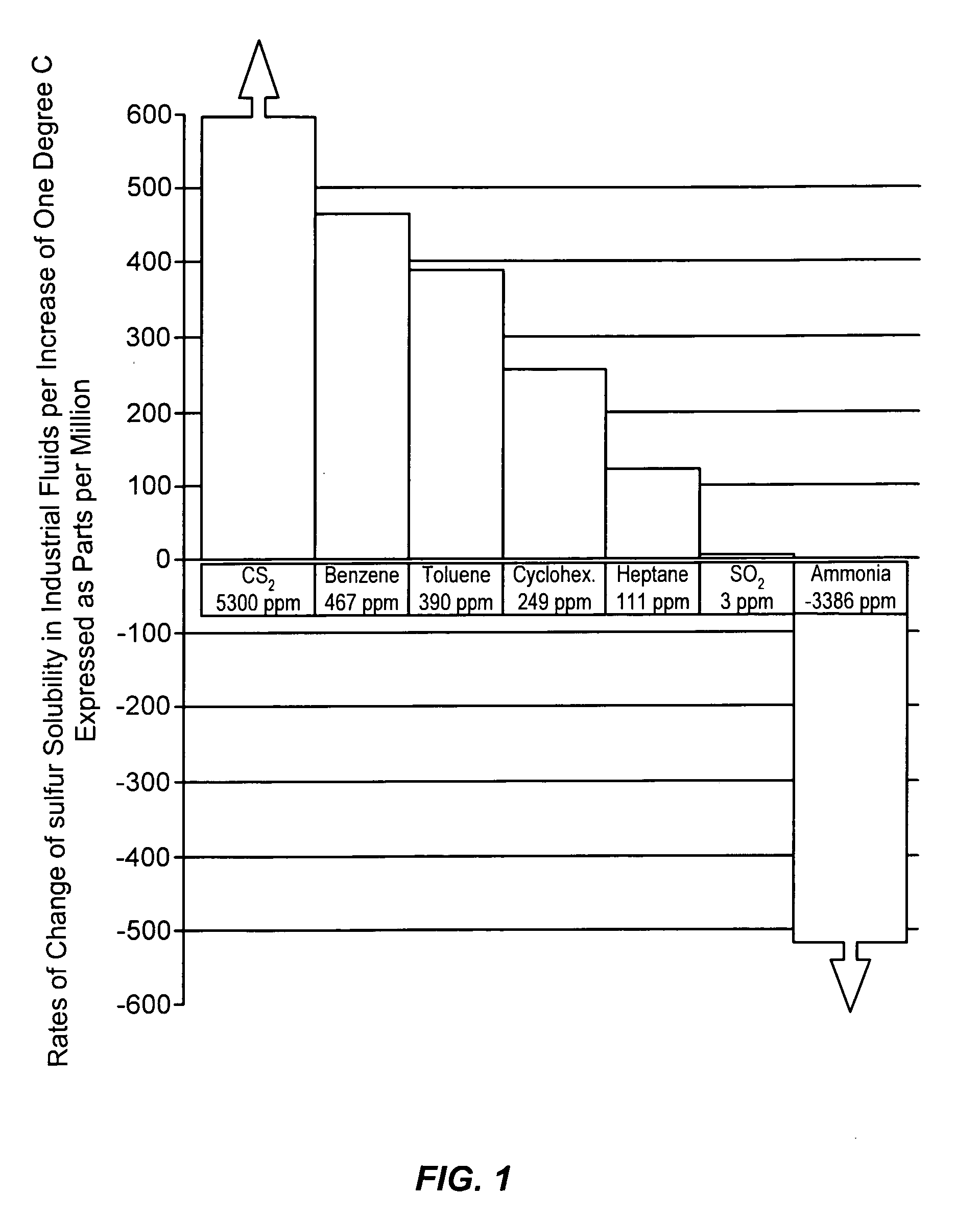
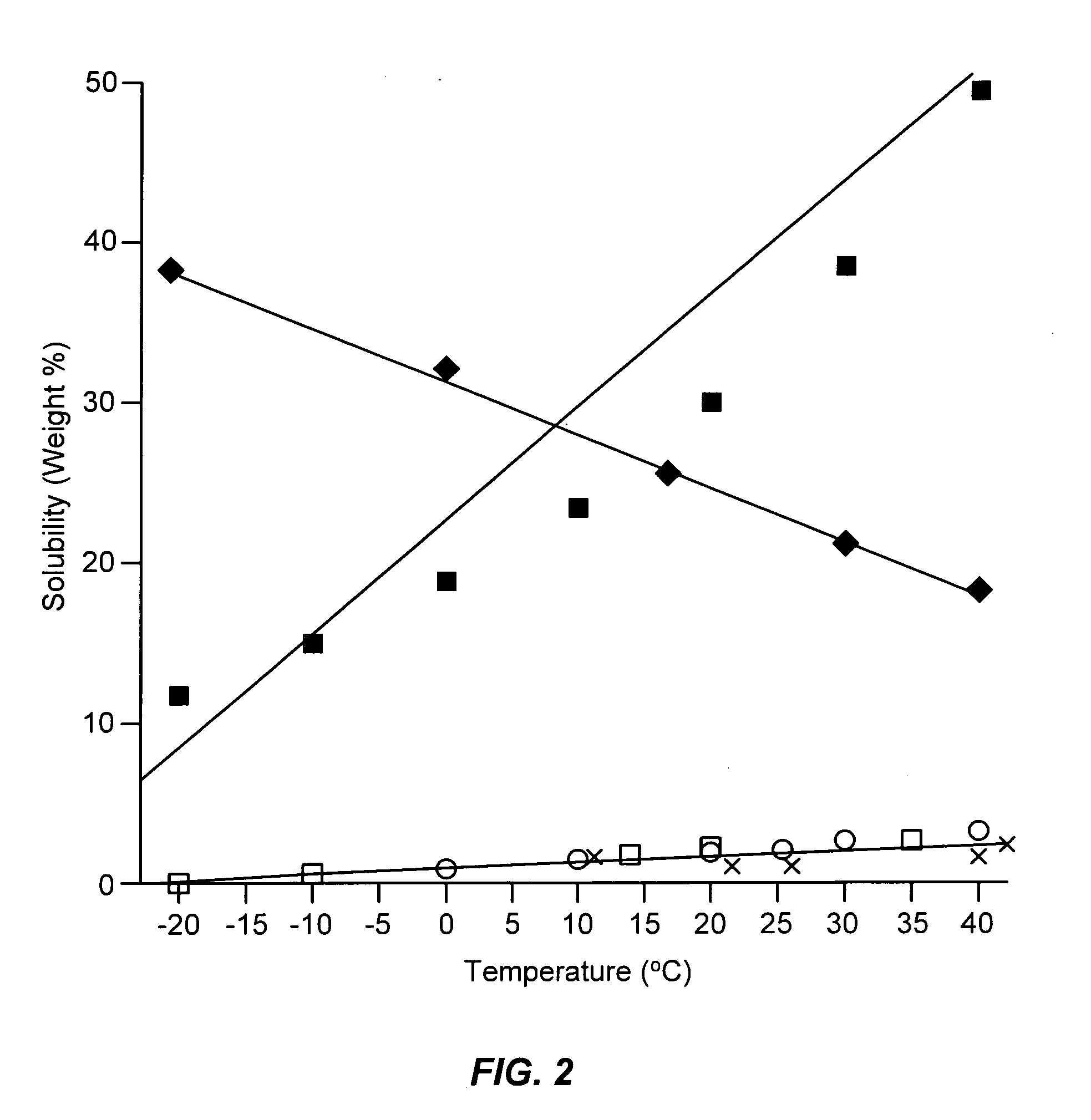
[0068]This example illustrates the solubility and fluidity characteristics of mixtures of sulfur and anhydrous ammonia at different temperatures.

[0069]Representative models of transport vessels were fabricated from clear 19 mm polyvinyl chloride Schedule 40 or Schedule 80 pipe in appropriate lengths to provide a capacity of approximately 100 mL per pipe section. Each section was capped at one end by solvent welding and adhesive techniques and a ball valve was placed on the other end. Each vessel was weighed to establish its tare and then charged with liquid anhydrous ammonia. The mass of ammonia thus added was then determined and a predetermined amount of sulfur was placed in a separate vessel of the same construction. The ammonia and sulfur vessels were then joined through their ball valves, and the valves were opened to combine the liquid ammonia and sulfur which were then mixed by rotation, inversion, and agitation of each vessel.

[0070]By observation it was determined that mixtur...

example 2

[0071]This example illustrates the pumping of solutions and slurries of sulfur in liquid anhydrous ammonia in a bench-scale model.

[0072]A bench-scale piping circuit was made from 19 mm diameter steel and transparent PVC pipe having a total circuit length of approximately 4 meters. The circuit contained a small pump and a ninety-degree downward angled steel U-joint of about 0.9 meter with a drain valve. The U-joint was placed at mid-circuit from the pump and was attached with appropriate isolation valves and detachable close couplings below the isolation valves. Three separate standing pipe sections were attached as Tees extending vertically upwards from the main circuit. These standpipes were placed at regular intervals between the pump and the downward U joint on one side of the circuit. The standpipes were 15 cm to 25 cm in height. The standpipe closest to the pump was fitted with a valve attachment leading to a vacuum pump. The second standpipe was fitted with a commercial ammoni...

example 3

[0082]This example presents a prospective illustration of a slurry pumping method, a solid sulfur storage method, a solid sulfur recovery method, and further screening experiments for shale oil, crude oils, coal, grain, and tar sands.

[0083]The dropping funnel method of transferring slurry to the pipe system described in Example 2 can be replaced with a valve-in-head cartridge filter container without the interior filter cartridge, placed in-line with a by-pass circuit. Sulfur can be loaded separately in the filter container and ammonia charged separately. At an appropriate time the ammonia is washed into the sulfur and thence into the circuit either as a slurry or as a simple solution. An in-line baffled static mixer and a paddle wheel flow indicator can also be used. The tendency of the system to form deposits can be determined by a steel tube dipped into an agitated slurry vessel while running a cold or hot heat transfer fluid through the tube.

[0084]To investigate applications of ...


PUM


Abstract

Elemental sulfur is combined with either liquid anhydrous ammonia, liquid sulfur dioxide, or both to form a solution or slurry which is transportable through pipelines or other transport vessels without a risk of clogging due to the environmental temperature drops that these vessels typically encounter. This unusual behavior and the advantages it offers arise from the discovery of unexpected solubility vs. temperature relationships of elemental sulfur in each of these two carriers. Among the advantages are significant improvements in the economics of many industrial chemical processes that involve the presence of sulfur either in elemental or chemically combined form, including natural gas or tar sands production and processing, hydrogen sulfide abatement, hydrogen production without carbon dioxide emissions, and sulfur extraction from ores, subterranean deposits, depositories, or fouled impaired industrial facilities. Large-scale ramifications for energy and fertilizer mineral resource utilization, greenhouse gas abatement, hydrogen economy, and nitrogen fertilizer production are taught.

Description

CROSS REFERENCE TO RELATED APPLICATION[0001]This application is related to U.S. Provisional Patent Application No. 60 / 476,082, filed Jun. 4, 2003, and claims all benefits legally capable of being offered by the provisional patent application. The entire contents of the provisional patent application are incorporated herein by reference.BACKGROUND OF THE INVENTION[0002]1. Field of the Invention[0003]This invention resides in the technologies associated with solutions and suspensions of sulfur and sulfur-containing compounds, with particular interest to methods of transport of sulfur by pipeline and other vessels where the deposition of solids is sought to be avoided, eliminated, or removed, or where solids are purposely deposited. Among the many areas of application of this invention are chemical processes that produce elemental sulfur as a product, chemical processes and products in which sulfur is used in combination with ammonia or other nitrogen compounds, and in the recovery of ...

Claims


Application Information

Patent Timeline
IPC IPC(8): B65G53/00B65G53/30C01B17/02C01B17/033C10L5/00
CPCC01B17/02C10L5/00C01B17/033Y02P20/10
Inventor STECHER, DANIEL G.
Owner STECHER PTY INTERESTS L L C
Learn More