
Manufacturing method of semiconductor substrate and semiconductor device

a manufacturing method and semiconductor technology, applied in semiconductor/solid-state device testing/measurement, manufacturing tools, instruments, etc., can solve the problems of loss of planarity of a surface of a single-crystalline semiconductor layer which is formed, increased crystal defects, and poor characteristics of a single-crystalline semiconductor layer formed using this single-crystalline semiconductor layer. , to achieve the effect of efficient manufacturing and efficient formation of favorable crystallinity and planarity

Inactive Publication Date: 2010-04-08
SEMICON ENERGY LAB CO LTD
View PDF22 Cites 14 Cited by
  • Summary
  • Abstract
  • Description
  • Claims
  • Application Information

AI Technical Summary

Benefits of technology

[0021]With the use of an embodiment of the present invention, regardless of variation of a laser and variation in thicknesses of single crystal semiconductor layers, the irradiation intensity of a laser beam to be emitted to the single crystal semiconductor layers can be optimized. Therefore, a single crystal semiconductor layer having favorable crystallinity and planarity can be manufactured efficiently.
[0022]A high-performance semiconductor element can be efficiently formed using a semiconductor substrate which is an embodiment of the present invention.

Problems solved by technology

In the case where a thin single crystal semiconductor layer is formed using a hydrogen ion implantation separation method, planarity of a surface of the single crystal semiconductor layer which is formed is lost because of ion implantation, a physical impact in separation, or the like, and crystal defects are increased.
For example, in the case where there are a large number of defects in the single crystal semiconductor layer, a defect level is easily formed at an interface with a gate insulating layer; therefore, characteristics of a semiconductor element formed using this single crystal semiconductor layer is not good.
When there is large unevenness on the surface of the single crystal semiconductor layer, it is difficult to form a gate insulating layer with a high withstand voltage, causing a decrease in performance of the semiconductor element such as a decrease in field effect mobility, an increase in a threshold voltage, and the like.
However, heating at a high temperature or treatment such as grinding and polishing is not appropriate for treatment on a single crystal semiconductor layer formed over a glass substrate.
However, the present inventors found through their research that, in the case where the irradiation intensity of a laser beam is too low, crystal defects are not sufficiently repaired, while in the case where the irradiation intensity of a laser beam is too high, problems occur in that planarity of a surface is lowered and part of a single crystal semiconductor layer is microcrystallized.
However, energy of a laser beam is very unstable, and even when laser beams are applied under the same settings using the same apparatus, energy of the laser beams varies every time due to apparatus condition.
In addition, in accordance with variation in thicknesses of single crystal semiconductor layers which are irradiated with laser beams, the optimum irradiation intensity of a laser beam varies each substrate; therefore, it is not easy to determine the intensity of the laser beam uniformly.

Method used


Image

  • Manufacturing method of semiconductor substrate and semiconductor device
  • Manufacturing method of semiconductor substrate and semiconductor device
  • Manufacturing method of semiconductor substrate and semiconductor device

Examples


embodiment 1

[0036]In this embodiment, a laser irradiation process of a single crystal semiconductor layer in a method for manufacturing a semiconductor substrate will be described.

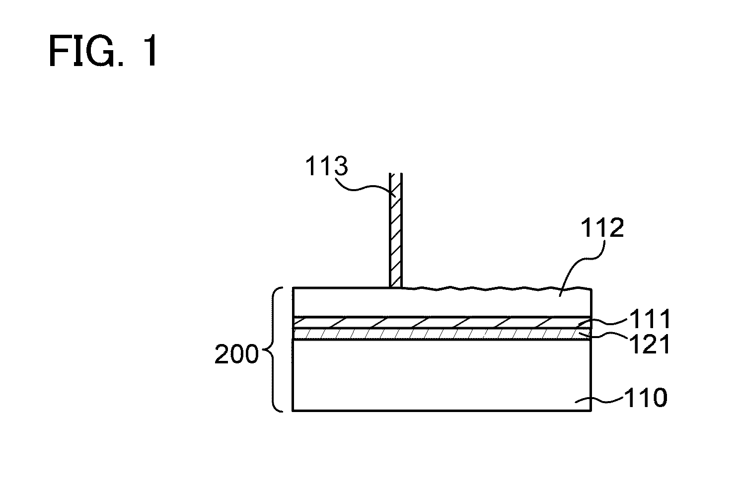
[0037]FIG. 1 illustrates a process in which a single crystal semiconductor layer 112 is irradiated with a laser beam 113. In FIG. 1, as for a semiconductor substrate 200 of this embodiment, the single crystal semiconductor layer 112 separated from a single crystal semiconductor substrate is provided over a base substrate 110 with a first insulating layer 111 and a second insulating layer 121 interposed therebetween. As described above, planarity of a surface of the single crystal semiconductor layer 112 which has been separated from the single crystal semiconductor substrate is lost because of ion introduction, a physical impact in separation, or the like. Note that as the single crystal semiconductor substrate, a single crystal silicon substrate, a germanium substrate, or a compound semiconductor substrate of gallium...

embodiment 2

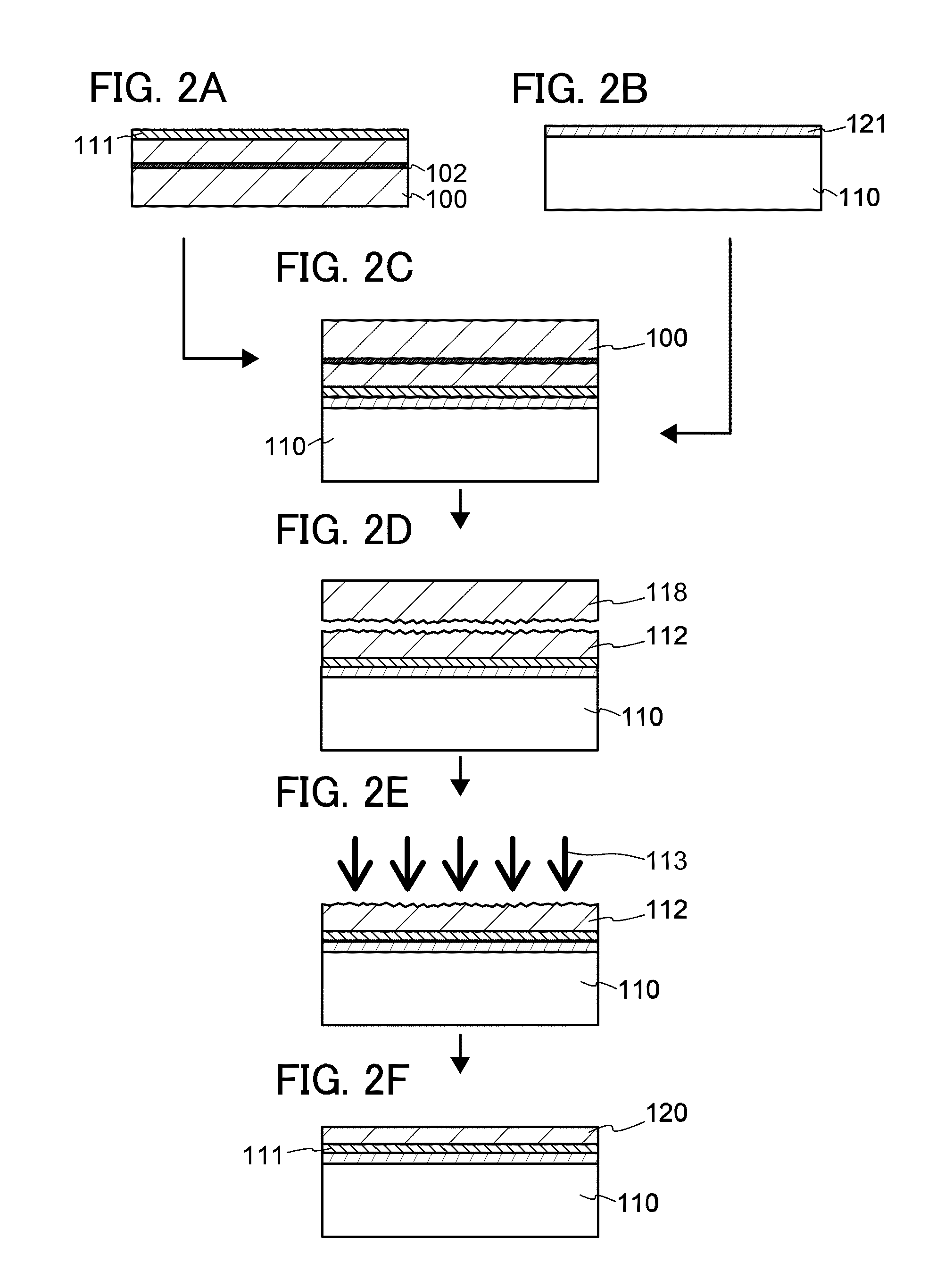
[0062]In this embodiment, a method for manufacturing a semiconductor substrate using the method for detecting an optimal condition for a laser beam described in Embodiment 1 will be described with reference to FIGS. 2A to 2F.

[0063]First, a single crystal semiconductor substrate 100 is prepared. As the single crystal semiconductor substrate 100, for example, a single crystal semiconductor substrate formed with an element belonging to Group 14 of the periodic table, such as silicon, germanium, silicon germanium, or silicon carbide can be used. Needless to say, a substrate made of a compound semiconductor such as gallium arsenide or indium phosphide may be used. In this embodiment, as the single crystal semiconductor substrate 100, a single crystal silicon substrate is used. Although there is no limitation on the shape and the size of the single crystal semiconductor substrate 100, for example, it is possible to process a circular semiconductor substrate of 8 inches (200 mm) in diamete...

embodiment 3

[0098]In this embodiment, a method for manufacturing a semiconductor device using the above-described semiconductor substrate will be described with reference to FIGS. 3A to 3D, FIGS. 4A to 4D, and FIGS. 5A and 5B. Here, a method for manufacturing a semiconductor device including a plurality of transistors is described as an example of the semiconductor device. Note that various semiconductor devices can be formed with the use of transistors described below in combination.

[0099]FIG. 3A is a cross-sectional view of a semiconductor substrate manufactured according to Embodiment 2.

[0100]To control threshold voltages of TFTs, a p-type impurity such as boron, aluminum, or gallium or an n-type impurity such as phosphorus or arsenic may be added to the single crystal semiconductor layer 120. A region where an impurity is added and a kind of the impurity to be added can be changed as appropriate. For example, a p-type impurity can be added to a formation region of an n-channel TFT, and an n...


PUM

PropertyMeasurementUnit
Fractionaaaaaaaaaa
Fractionaaaaaaaaaa
Fractionaaaaaaaaaa

Abstract

To provide a semiconductor substrate in which a semiconductor element having favorable crystallinity and high performance can be formed. A single crystal semiconductor substrate having an embrittlement layer and a base substrate are bonded with an insulating layer interposed therebetween; the single crystal semiconductor substrate is separated along the embrittlement layer by heat treatment; a single crystal semiconductor layer is fixed to the base substrate; the single crystal semiconductor layer is irradiated with a laser beam; the single crystal semiconductor layer is in a partially melted state to be recrystallized; and crystal defects are repaired. In addition, the energy density of a laser beam with which the best crystallinity of the single crystal semiconductor layer is obtained is detected by a microwave photoconductivity decay method.

Description

BACKGROUND OF THE INVENTION[0001]1. Field of the Invention[0002]The present invention relates to a method for manufacturing a semiconductor substrate provided with a single crystal semiconductor layer over a base substrate having an insulating surface. In addition, the present invention relates to a semiconductor device manufactured using the semiconductor substrate.[0003]2. Description of the Related Art[0004]In recent years, an integrated circuit using an SOI (silicon on insulator) substrate in which a thin single crystal semiconductor layer is formed on an insulating surface, instead of a bulk silicon wafer has been developed. By utilizing characteristics of a thin single crystal silicon layer formed over an insulating film, transistors formed in the integrated circuit can be electrically separated from each other completely. Further, each transistor can be formed as a fully-depleted transistor, and thus a semiconductor integrated circuit with high added value such as high integr...

Claims


Application Information

Patent Timeline
IPC IPC(8): H01L27/12H01L21/762B23K26/00H01L21/02H01L21/265H01L21/322H01L21/336H01L29/786
CPCH01L21/76254H01L29/78603H01L21/84H01L27/12B23K26/0622H01L21/02H01L21/265
Inventor MOMO, JUNPEINEI, KOSEIHONDA, HIROAKIKOYAMA, MASAKISHIMOMURA, AKIHISA
Owner SEMICON ENERGY LAB CO LTD
Learn More