
Magnetic material for high frequency wave, and method for production thereof

a high-frequency wave and magnetic material technology, applied in the field of magnetic material for a high-frequency wave, can solve the problems of difficult utilization of ferrites, difficult to cope with problems, and environmental degradation caused by electromagnetic waves released outwardly from high-frequency devices, and achieves small eddy current loss and high magnetic permeability.

Inactive Publication Date: 2010-03-18
ASAHI KASEI KK +1
View PDF7 Cites 30 Cited by
  • Summary
  • Abstract
  • Description
  • Claims
  • Application Information

AI Technical Summary

Benefits of technology

[0103]As a sub-phase in an R—Fe—N based magnetic material, an R—Fe alloy raw material phase, a hydride phase, a decomposed phase containing an Fe nanocrystal, an oxidized amorphous phase and the like may be contained, but in order to fully exhibit the advantage of the present invention, the volume fraction must be suppressed to a lower content than that of a main phase, and the content of the main phase exceeding 75% by volume with respect to the total of the R—Fe—N based magnetic material is very preferable from a practical standpoint. The main phase of an R—Fe—N based magnetic material is produced in such a way that nitrogen is intruded in between lattices of an R—Fe alloy of a main raw material phase, and crystal lattices expand in many cases, but the crystal structure has the nearly same symmetry as the main raw material phase.
[0104]The volume fraction used here refers to a proportion of a volume which a certain component occupies with respect to the total volume including voids of a magnetic material.
[0105]The main raw material phase used here refers to a phase containing at least R and Fe and not containing N, and having the rhombohedral, hexagonal or tetragonal crystal structure (here, a phase having a composition other than the above composition or another crystal structure and not containing N is referred to as a sub-raw material phase.).
[0106]Along with the expansion of crystal lattices due to intrusion of nitrogen, the antioxidative performance, or one or more of magnetic characteristics and electric characteristics are improved to make an R—Fe—N based magnetic material which is preferable from a practical standpoint. For the first time after this nitrogen incorporation process, a preferable magnetic material for a high frequency wave is made, and develops electromagnetic characteristics entirely different from conventional R—Fe alloys and Fe, which contain no nitrogen.
[0107]For example, in the case of selecting Pr10.5Fe89.5 having the rhombohedral structure as a main raw material phase of an R—Fe component base alloy, the incorporation of nitrogen increases the electric resistivity and improves magnetic characteristics including the Curie point, the magnetic permeability and the absolute value of the magnetic anisotropy energy, and the antioxidative performance.
[0108]The rare earth-iron-nitrogen based magnetic material of the present invention is preferably a material utilizing the in-plane magnetic anisotropy of the magnetic material. The in-plane magnetic anisotropic material is a material which is energetically more stable with the magnetic moment present on the c plane than with the magnetic moment present on the c axis. Therefore, Ha2>Ha1 is required. As indicated in the relational expression (5), when Ha2 / Ha1 becomes larger, a high magnetic permeability at the higher frequency can be achieved. That is, the material of the present invention is desirably a material having Ha1 of 0.01 to 106 A / m, Ha2 of 10 to 1010 A / m and Ha2>Ha1. However, the natural resonance frequency of a material is represented by the relational expression (6), and when the absorbed electromagnetic wave reaches a high frequency, a product of Ha2Ha1 becomes important, and it is important that this magnitude is between 0.7 to 7×10¹³ [A2 / m2].[Expression 6]fr=4πν√{square root over (Ha2 Ha1)}  (6)

Problems solved by technology

On the other hand, the electromagnetic environmental deterioration caused by electromagnetic waves released outwardly from high-frequency devices is seen as a problem, and the movement of law regulations by public institutions and international institutions, and self-imposed regulations is currently being activated.
However, since there is a contradictory causal relation in which signals useful in individual devices give trouble to other devices and living bodies, the problem is very difficult to cope with.
The frequencies of electromagnetic noises have recently reached the ultrahigh frequency field of GHz, and utilization of ferrites conventionally used has become difficult.
Hence, in the case of using metal materials in a high frequency field, a high magnetic permeability cannot be achieved up to a high frequency.
Further, in an ultrahigh frequency field exceeding 1 GHz, even in such composite materials, the magnetic permeability unavoidably decreases by the influence of eddy-current loss.
Therefore, in the case of using sendust at 1 GHz or higher, the grain diameter must be made approximately less than 2 μm, but pulverization by an industrially available mechanical method can almost hardly achieve such a diameter.
Although metal-based magnetic bodies imparted form-anisotropy are also used, the thickness of the metal-based magnetic fillers must be made also less than 0.2 μm according to the same reasons as the powder described above, the metal-based magnetic bodies have a limit to applications to ultrahigh frequency usage even if the magnetic permeability is made large by increasing the filling factor to some extent.
However, even in that case, the electromagnetic absorption in high frequency and ultrahigh frequency fields cannot be developed without designing materials such that the eddy-current loss fails to become remarkable in a low frequency field.
Although the magnetic permeability is high, films of only several micrometers as a whole can be fabricated; a sufficient noise absorption power cannot be achieved; and the cost is high.
As a result, the above developments have not yet been put to practical use.
However, the ferrite thin film does not have a magnetic permeability sufficient for ultrahigh frequency applications, and the film forming rate cannot be said to be satisfactory for mass production of smooth thin film materials in μm units.
However, the soft magnetic hexagonal magnetoplumbite ferrite material also has an electric resistivity which cannot be made sufficiently high for the required performance, and has an obstacle of a large eddy-current loss.
As a result, this ferrite material has not yet been put to practical use.
And ferrite-based oxide magnetic materials having a high electric resistivity have a small problem with eddy-current loss, but have an important problem of not providing a sufficient magnetic permeability; by contrast, the metal-based magnetic materials have a high magnetic permeability, but a low electric resistivity, so they have a problem of causing the eddy-current loss at a low frequency band; thus, both have problematical points of not being suitable as magnetic materials for high frequency applications.

Method used


Image

  • Magnetic material for high frequency wave, and method for production thereof
  • Magnetic material for high frequency wave, and method for production thereof
  • Magnetic material for high frequency wave, and method for production thereof

Examples


example 1

[0266]Nd of 99.9% in purity and Fe of 99.9% in purity were melted and mixed in an arc melting furnace in an argon gas atmosphere and then, an ingot of 5 mm in thickness was fabricated by the drop cast method. The ingot was annealed in an argon atmosphere at 1,030° C. for 20 hours, slowly cooled, and subjected to a surface polishing to prepare a raw material alloy having a composition of Nd11.6Fe88.4.

[0267]The raw material alloy was pulverized by a jaw crusher, and then further pulverized by a cutter mill in an argon atmosphere, and the grain size was regulated by a sieve to obtain a powder of approximately 60 μm in average grain diameter. The Nd—Fe raw material alloy powder was charged in a horizontal tubular furnace, and subjected to a heat treatment at 420° C. in a mixed gas flow having an ammonia partial pressure of 0.35 atm and a hydrogen gas partial pressure of 0.65 atm for 1 hour to adjust the alloy powder into an Nd10.1Fe76.7N13.2 composition of approximately 30 μm in average...

example 2

[0279]The course powder of the Nd10.1Fe76.7N13.2 composition obtained in Example 1 was subjected to a rotation ball mill in argon having an oxygen partial pressure of 1%, surface-treated in a ferric chloride solution of pH 6.2, and thereafter subjected to a surface oxidation treatment under pH regulation to obtain a rare earth-iron-nitrogen (-hydrogen-oxygen) based magnetic material of Nd8.0Fe60.8N10.6H7.8O12.8 having an average grain diameter of 6 μm.

[0280]This material was blended with 12% by mass of an epoxy resin, molded in a static magnetic field of 1.2 MA / m (uniaxial magnetic field orientation) at a molding pressure of 1 GPa into a size of 10×5×1.3 mm, and cured at 150° C. for 2 hours. The obtained molding had a density of 5.2 and a volume fraction of the magnetic material of 62% by volume.

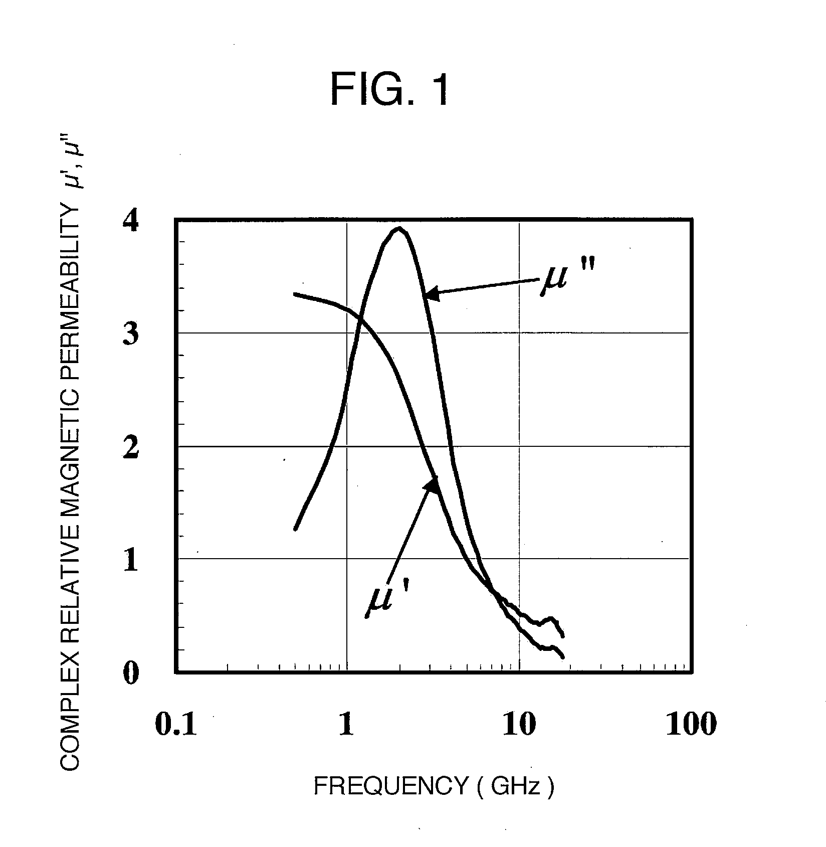
[0281]The maximum value of the imaginary term of the complex relative magnetic permeability in the case where the magnetic field orientation direction of the rare earth-iron-nitrogen based m...

example 3 and 4

[0283]Nd of 99.9% in purity and Fe of 99.9% in purity were melted and mixed in a high frequency melting furnace in an argon gas atmosphere and then, annealed in an argon atmosphere at 950° C. for 100 hours, slowly cooled, and subjected to a surface polishing to prepare a raw material alloy having a composition of Nd10.5Fe89.5.

[0284]The raw material alloy was pulverized by a jaw crusher, then pulverized by a pin mill in an argon atmosphere, and thereafter, the grain size was regulated by an acoustic classifier to obtain a powder of 50 μm in average grain diameter.

[0285]This Nd—Fe raw material alloy powder was charged in a horizontal tubular furnace, subjected to a heat treatment at 420° C. in a mixed gas flow having an ammonia partial pressure of 0.35 atm and a hydrogen gas partial pressure of 0.65 atm for 2 hours, and then annealed at 400° C. in argon gas for 30 min to adjust the powder alloy into an Nd9.1Fe77.3N13.6 composition of approximately 25 μm in average grain diameter.

[0286...


PUM

PropertyMeasurementUnit
Temperatureaaaaaaaaaa
Fractionaaaaaaaaaa
Fractionaaaaaaaaaa

Abstract

Disclosed is a magnetic material for a high frequency wave which has high magnetic permeability and small eddy-current loss, particularly a magnetic material for a high frequency wave which can be used suitably in an information device which works in a high frequency field of 1 GHz or higher. Specifically disclosed is a composite magnetic material for a high frequency wave, which comprises a (rare earth element)-(iron)-(nitrogen)-based magnetic material and a (rare earth element)-(iron)-(nitrogen)-based magnetic material whose surface is coated with a ferrite magnetic material.

Description

TECHNICAL FIELD[0001]The present invention relates to a magnetic material for a high frequency wave, particularly a composite magnetic material for a high frequency wave and a magnetic material-resin composite material for a high frequency wave, including magnetic materials used in transformers, heads, inductors, reactors, magnetic cores, yokes, antennas, microwave devices, magnetostriction devices, magnetoacoustic devices and magnetic recording devices which are used mainly in power equipment and information-communications related devices and which are used in high or ultrahigh frequency fields, and sensors through magnetic fields such as Hall elements, magnetic sensors, electric current sensors, rotation sensors and electronic compasses; further magnetic materials to suppress interruptions by unnecessary electromagnetic interference, such as electromagnetic noise absorbing materials, electromagnetic wave absorbing materials and materials for magnetic shield; and magnetic materials...

Claims


Application Information

Patent Timeline
IPC IPC(8): B32B5/00B32B15/00B05D5/12H01F1/00H01F1/28
CPCB82Y30/00Y10T428/265C01B21/082C01G49/00C01G49/0018C01G49/009C01P2002/52C01P2004/62C01P2004/64C01P2006/10C01P2006/40C01P2006/42C01P2006/80C04B35/58042C04B35/5805C04B35/6261C04B35/62805C04B35/62897C04B35/645C04B35/6455C04B2235/3852C04B2235/3895C04B2235/40C04B2235/405C04B2235/465C04B2235/5436C04B2235/666C22C45/02H01F1/0593H01F1/0596H01F1/33H01F41/0273Y10T428/32C01B21/0602H01F1/26H01F1/14
Inventor IMAOKA, NOBUYOSHIABE, MASANORINAKAGAWA, TAKASHITADA, SASARU
Owner ASAHI KASEI KK
Learn More