
Method for forming bond between different elements

a technology of metal bonding and metal parts, applied in the direction of nitrogen oxide/oxyacid, sustainable manufacturing/processing, final product manufacturing, etc., can solve the problems of unstable transistor characteristics, low mobility disadvantage, and inability to stabilize the characteristics of such semiconductors at all, so as to achieve high energy, high energy component, and high conductivity

Inactive Publication Date: 2012-12-20
NISSAN CHEM IND LTD
View PDF3 Cites 6 Cited by
  • Summary
  • Abstract
  • Description
  • Claims
  • Application Information

AI Technical Summary

Benefits of technology

[0044]The present invention enables doping that forms a stable amorphous silicon film and a stable polycrystalline silicon film at a low temperature and simultaneously that imparts conductivity in an atmospheric pressure environment.
[0045]The present invention relates to a technique for forming a bond between different metals using low-temperature atmospheric-pressure plasma jet, and in particular, relates to a technique useful for doping with a Group 13 element or a Group 15 element into a silicon film using an oligosilane compound that can form a film through coating.
[0046]In other words, chemical reaction by plasma is controlled by the control of plasma jet that is in an ionized gas state and has high energy by gas pressure and electric field, and this enables doping of a silicon thin film with a different element near atmospheric pressure and at low temperature.
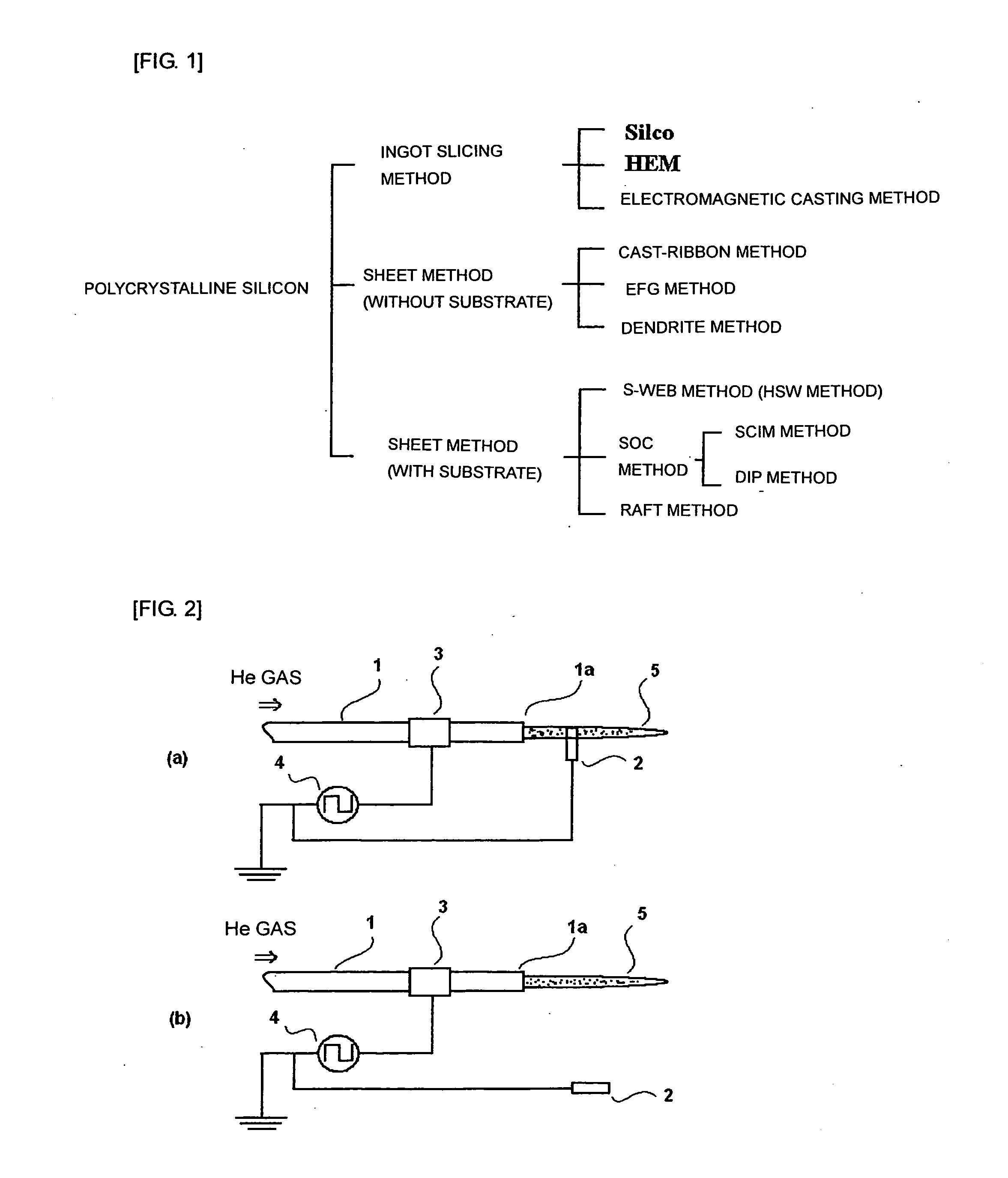
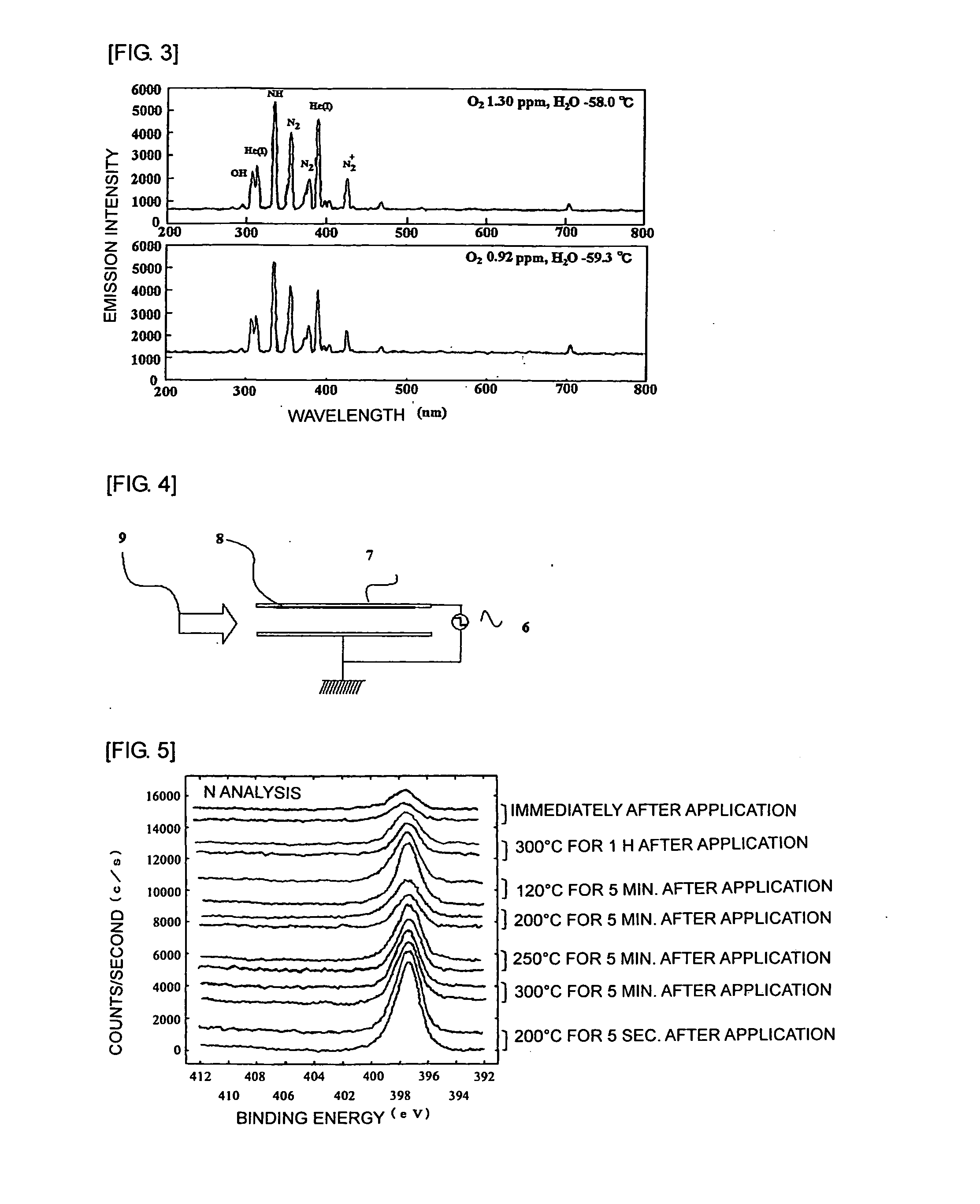
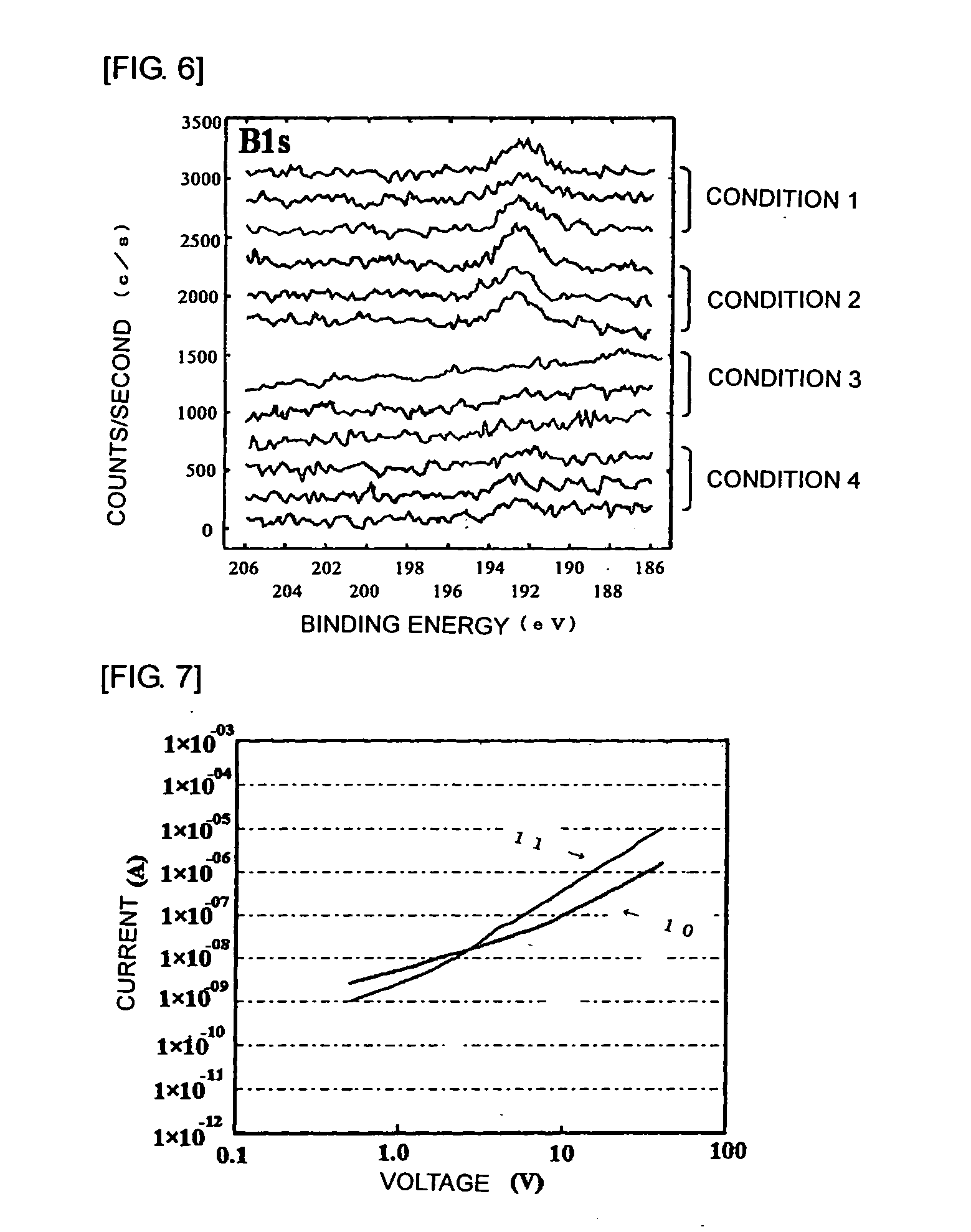
[0047]As a whole, plasma that is at low temperature but has a high energy component with high reactivity and is in a non-equilibrium state, is generated at a pressure not less than the steam pressure of a liquid, that is, at a pressure around atmospheric pressure. By application of a mixed solution of a boron hydride compound and an oligosilane compound and subsequent spin coating, a thin film is formed. The plasma is applied to the thin film to remove hydrogen so that silicon and boron are directly bonded. The treatment can be continuously performed because an ambient pressure process using the ambient pressure (atmospheric pressure) plasma does not need vacuum. Furthermore, helium gas that is readily ionized is used for plasma generation. In addition, the treatment can be performed at a low temperature, and hence the treatment can be performed without damage to a substrate. Therefore, the technique can be applied to various substrates. The technique is used for producing a solar cell, a transistor, and various sensors including a silicon semiconductor as a basic component in an atmospheric pressure environment through a low temperature wet process. The technique enables the formation in a low temperature process. Therefore, the technique is useful for weight reduction of devices and useful as a technique for production of plastic devices.

Problems solved by technology

However, at that time, a silicon TFT exhibited no characteristic, and compound semiconductors such as CdS were used, but the characteristics of such semiconductors were not stabilized at all.
This raises an intrinsic problem of stoichiometry and a problem of unstable transistor characteristics due to the contact condition between a gate insulating film and a CdSe interface.
The (a-Si:H) TFT has a small off-state current and can ensure a high on / off current ratio but is considered to have a disadvantage of a low mobility.
However, the film is formed in a large electric field, the electrode surface is accordingly subjected to a strong impact of positive ions, and it is very difficult to obtain a smooth surface.
However, it seems to be disadvantageous for the plasma CVD method that the substrate is affected by the ion impact even in such installation manner.
Such a liquid phase method needs high temperature treatment because a molten silicon is typically used, and hence the method needs a large system.
However, the crystal grain boundary obtained by such a method is normally very small, and hence the product cannot be used without treatment.

Method used


Image

  • Method for forming bond between different elements
  • Method for forming bond between different elements
  • Method for forming bond between different elements

Examples


synthesis example 1

Synthesis of Catalyst, Diphenyl Dicyclopentadienyl Zirconium Cp2ZrPh2

[0113]In a nitrogen atmosphere, into a 300-mL reaction flask, dichloro dicyclopentadienyl zirconium Cp2ZrCl2 (5.0 g) and 39 mL of DME (1,2-dimethoxyethane) as a solvent were charged, and the temperature of the mixture was set to 0 to 10° C. To the mixture, 34.37 mL of solution of phenylmagnesium bromide (PhMgBr) in THF (tetrahydrofuran) having a concentration of 37.1 mol / L was added dropwise at the same temperature, and the whole was stirred at 24 to 26° C. for 19 hours. The reaction mixture was concentrated under reduced pressure at 20° C. / 20 Torr, then 8 mL of diethyl ether (Et2O) was added, and the whole was stirred at 24 to 26° C. for 1 hour. To the resultant mixture, 39 mL of toluene was further added, then the whole was stirred at the same temperature for 30 minutes, and the reaction solution was filtered. The filtrate was concentrated under reduced pressure at 20° C. / 10 Torr, and the obtained solid was wash...

synthesis example 2

Synthesis of Polyphenylsilane

[0114]In a nitrogen atmosphere, into a 100-mL reaction flask, diphenyl dicyclopentadienyl zirconium Cp2ZrPh2 (0.165 g) synthesized in Synthesis Example 1 was charged as a catalyst, then phenylsilane PhSiH3 (10 g) was added to the catalyst at 24 to 26° C., and the mixture was stirred at the same temperature for 89 hours. To the resultant mixture, toluene (47 g) was added, then 3% HCl (68 g×5 times) was added, and the whole was stirred and washed. The organic phase was separated, then ion-exchanged water (68 g) was added, and the whole was stirred and washed. The organic phase was purified by Florisil (27 g) column chromatography using toluene (118 g) as an eluant followed by concentration, and the product was dried at 80° C. for 2 hours to yield polyphenylsilane (8.87 g) as a target compound. The obtained polyphenylsilane was composed of a chain polyphenylsilane corresponding to Formula (1) and a cyclic polyphenylsilane corresponding to Formula (2) in a m...

synthesis example 3

Synthesis of Polyhydrosilane

[0115]To a 100-mL brown reaction flask, polyphenylsilane (5.0 g) synthesized in Synthesis Example 2 and cyclohexane (43.5 g) as a solvent were charged. To the mixture, aluminum chloride AlCl3 (0.41 g) was added, and the whole was solidified with liquid nitrogen. The temperature of the mixture was raised to room temperature in a water bath followed by nitrogen substitution. Into the mixture, hydrochloric acid HCl gas was blown at a flow rate of 950 mL / min for 10 hours. Then, decompression and pressure return by nitrogen were repeated 10 times to remove hydrochloric acid HCl. To the mixture, 13.72 g of solution containing lithium aluminum hydride LiAlH4 (1.17 g) in diethyl ether (Et2O) was added dropwise at 0 to 10° C. over 30 minutes in a nitrogen atmosphere. The whole was stirred at room temperature for 12 hours, and the reaction solution was poured into ion-exchanged water (11 g). The mixture was stirred for 1 minute and left. Then, the supernatant liqui...


PUM

PropertyMeasurementUnit
output voltageaaaaaaaaaa
frequencyaaaaaaaaaa
temperatureaaaaaaaaaa

Abstract

The present invention provides a doping technique that forms a stable amorphous silicon film and a stable polycrystalline silicon film at a low temperature and simultaneously that imparts conductivity in an atmospheric pressure environment. A method for producing a compound containing a bond between different elements belonging to Group 4 to Group 15 of the periodic table, the method included: applying, at a low frequency and atmospheric pressure, high voltage to an inside of an electric discharge tube obtained by attaching high-voltage electrodes to a metal tube or an insulator tube or between flat plate electrodes while passing an introduction gas, so as to convert molecules present in the electric discharge tube or between the flat plate electrodes into a plasma; and applying the plasma to substances to be irradiated, the substances to be irradiated being two or more elementary substances or compounds.

Description

TECHNICAL FIELD[0001]The present invention relates to a technique for forming a bond between different metals using low-temperature atmospheric-pressure plasma jet and, in particular, relates to a technique useful for doping with a Group 13 element or a Group 15 element into a silicon film using a polysilane compound and an oligosilane compound that can form a film through coating.BACKGROUND ART[0002]A silicon semiconductor is a material that has been studied as materials for a thin film transistor (TFT) and a solar cell since a long time ago. In particular, the TFT has been studied for a long time. In 1930, Lilienfeld et al. developed it as a current control device, and then in 1945, a vacuum deposited silicon thin film was observed to have a slight TFT action. Bardeen et al. examined the characteristic evaluation to lead to a suggestion in which an electric field to a semiconductor surface due to a gate potential is shielded by surface level, causing surface carriers not to be sub...

Claims


Application Information

Patent Timeline
Patent Type & Authority Applications(United States)
IPC IPC(8): B01J19/08C01B21/00
CPCH01L21/0242H01L21/02532H01L21/02576H01L21/02579H01L21/02592Y02E10/546H01L21/2254H01L31/0288H01L31/182H01L31/20H05H2245/123H01L21/02628C08J2383/16Y02P70/50H05H2245/40H01L21/02274B01J19/081B01J19/087C08J3/28
Inventor FURUSHO, HITOSHINOHARA, YUKIWATANABE, HISAYUKIGOTO, YUICHI
Owner NISSAN CHEM IND LTD
Learn More