
Metallic components for use in corrosive environments and method of manufacturing

a technology for corrosive environments and metal components, applied in heat treatment furnaces, heat treatment equipment, furnaces, etc., can solve the problems of failure of metallic components, the rate at which corrosive related failure processes occur, and the degradation of metallic components, so as to improve the surface finish, the effect of reducing the cost and increasing the applied stress

Inactive Publication Date: 2011-09-15
SURFACE TECH HLDG
View PDF28 Cites 9 Cited by
  • Summary
  • Abstract
  • Description
  • Claims
  • Application Information

AI Technical Summary

Benefits of technology

[0020]The present invention relates generally to corrosive resistant components, such as Fuel Recovery Components as well as components used in a wide variety of chemical plant applications, and their method of manufacture. Such corrosive resistant components have improved stress corrosion and fatigue properties for mitigating or preventing the deleterious effects of SCC and fatigue on useful life of the metallic components.
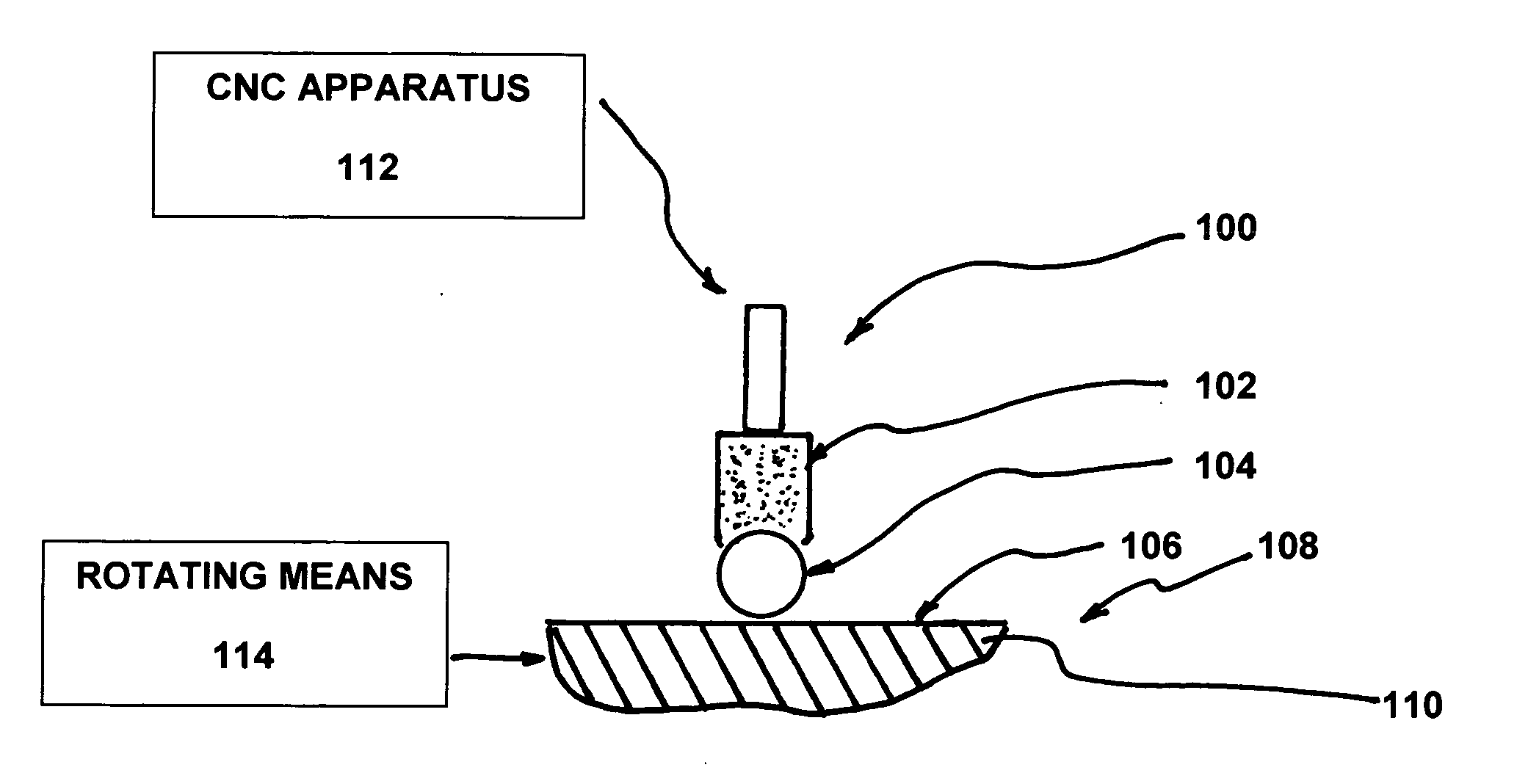
[0021]The preferred method of the invention disclosed herein dramatically improves the SCC, corrosion fatigue, and general fatigue performance of metallic components used in a wide variety of applications, such as fossil fuel recovery and chemical plant applications, manufactured from traditional low-cost alloys, such as carbon steel, without altering either the alloy chemical composition or the geometry of the component. The invention puts the surface of the metallic component that is in contact with the corrosive environment, and the layer of material immediately below the surface, into a state of high residual compression with controlled low cold working to a sufficient depth to encompass the surface irregularities. In a preferred embodiment, the components include tubular products such as pipe, tubing, casing, and couplings, having the outside, or inside, or both surfaces processed using various machine tools or robots commonly available that can be used to position and move the burnishing tools to cover all or a portion of the surface being treated. In a preferred embodiment of the invention, a preferred method includes a surface treatment which is performed in a single automated operation during initial manufacture or during repair and overhaul of existing components.
[0022]In a preferred embodiment of the invention, a layer of compression is created using one or more ball or roller burnishing tools and normal forces and tool positioning that produce a relatively uniform layer of compression extending to a depth of about 1 mm or more, so that the surface being treated when in contact with a corrosive media and any surface irregularities, such as discussed above, are confined in a layer of compressive residual stress. The magnitude of the residual compression is generally on the order of the yield strength of the alloy so that the surface layer remains in compression under any applied tensile stresses experienced by the component during service, and the stress at the surface in contact with the corrosive environment never exceeds the critical tensile threshold for SCC. In a preferred embodiment, scratches and other surface irregularities are maintained in compression, even under external applied tensile loading during service, thereby fatigue initiation is prevented or significantly reduced.
[0024]Processing by the method of this invention allows inexpensive steel or alloy to be used for components that operate in a corrosive environment, such as Fuel Recovery Components as well as components used in a wide variety of chemical plant applications (such as piping, casing, couplings and related components), that are normally restricted to use only in applications not subject to SCC, to then be placed in service in corrosive environments, such as in “sour” wells, and applications previously requiring more costly alloys, such as stainless steels. Inexpensive steels processed by the method of this invention can then be used at their optimum temper and strength to allow higher applied stresses in service allowing drilling of deeper wells at lower cost.
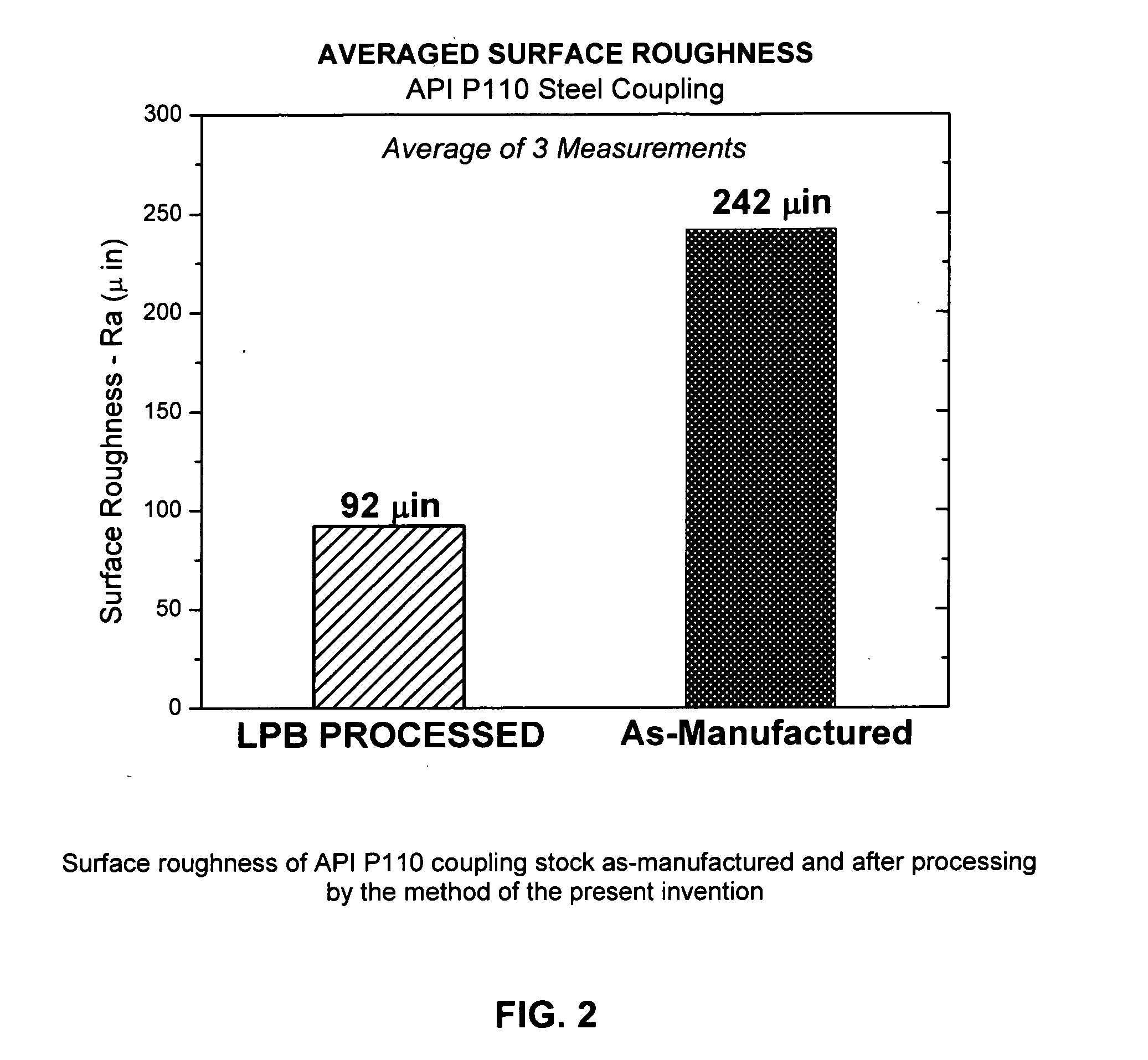
[0025]In a preferred embodiment, the surface finish is improved by burnishing with a finely finished tool to both reduce surface irregularities while enhancing the detection limits of NDI. Improved NDI detection limits reduce inspection costs and allow more reliable detection of flaws. Elimination or the reduction of surface irregularities improves both SCC and fatigue resistance, as noted above.

Problems solved by technology

In the recovery and distribution of fossil fuels and the operation of petrochemical refineries and other types of chemical plants, failure of metallic components is often a result of the combination of stress as well as one or more corrosive elements, such as hydrogen sulfide, H2S, ammonia, or chlorine, to which the component is exposed in service.
The elevated temperatures, pressures, and applied stresses, either static or alternating, to which such components are exposed, contribute to their degradation and the rate at which corrosive related failure processes occur, especially SCC and corrosion fatigue.
The life of metallic components in these environments and applications is often limited, and premature component failures restrict production and increase operational costs.
In oil and natural gas well drilling to recover fossil fuels, the depth to which drilling can be performed is limited by the materials available for the drill pipe, tubing, and casing, generally referred to as Oil Country Tubular Goods (OCTG).
In offshore drilling, the material strength of the OCTG and drill components limits the depth of water and thus the distance from shore that is accessible.
Therefore, the strength of metallic material that can be used in a SCC prone environment, such as environments that Fuel Recovery Components often operate in, is limited.
The failure of Fuel Recovery Components as well as components used in a wide variety of chemical plant applications generally results in major economic loss, if not catastrophic damage impacting public safety.
It is well known that failure of such metallic components is most commonly caused by the mechanisms of SCC or fatigue.
Fatigue failures occur under the influence of alternating applied stress, generally accompanied by a steady mean stress, and often originate from a surface flaw such as a corrosion pit, SCC, or scratch.
All of these chemistry or coating-based methods have limitations, or have shown limited improvement in performance at relatively high implementation costs to the end-user.
Components formed from corrosion resistant alloys are relatively expensive and often are not cost effective.
Paint and coatings will peal, wear away, or be scraped off eventually exposing the surface to the corrosive environment, and generally cannot be renewed on the casing and components installed down in the well.
Reducing the strength of the material and designing for lower applied stresses provides a long-term solution but limits performance, as noted above.
However, because it is a random impact process, shot peening severely cold works the surface in order to cover the surface with impact dimples and produce the compressive layer.
The beneficial compressive residual stresses in the highly cold worked surface are then known to be susceptible to rapid thermal relaxation at relatively lower service temperatures and is therefore unacceptable for certain components.
Further, the relatively shallow cold worked residual compression layer is also susceptible to loss of compression by tensile overload in work hardening materials, again making the method unacceptable for certain components.
Shot peening also produces a roughened dimpled surface that makes it more difficult to detect a crack or flaw using nondestructive inspection (NDI) methods such as ultrasonic and eddy current means, again making it unacceptable for certain applications.
LSP can produce relatively deep (˜1 mm) compression, but is prohibitively expensive for components having large surface areas needing treatment.
Further, LSP requires an ablative coating to be applied along the surface of the component being treated that generates post-processing debris that must be removed, thereby adding additional cost.
In addition, LSP requires repeated shocking cycles to achieve a 1 mm deep compressive layer, thereby adding additional cost and process time.
Also, LSP has been known to damage the surface in three ways that have been shown to contribute to component failure.
First, internal cracking can occur due to superposition of echoing shock waves.
Second, LSP shock waves are known to cause twinning in some crystals, like in titanium alloys, that are associated with subsequent fatigue crack initiation.
Third, LSP is known to produce laser burns and local areas of residual tension that occur if the ablative coating is breached so that the laser strikes the bare metal surface; surface tension from such burns will exacerbate SCC.
Accordingly, components treated using LSP often require post-processing inspection that can significantly increase cost and processing time.
Components that have been damaged by the LSP process often require additional processing or must be scrapped, thereby further increasing cost and processing time.
Further, denting of the surface at each shock point by LSP may also require refinishing operations.
Like shot peening, the dented surface reduces the effectiveness of eddy current and ultrasonic NDI techniques that are vital to monitor the integrity of critical components.
Cold working, however, is well known to increase the susceptibility of metals to SCC.
However, such processes increase processing time and cost and may be difficult to perform on certain components.
Both SCC and fatigue failures are well known to initiate from very small surface irregularities such as surface cracks, small crevices, flaws, scratches, persistent slip bands, even crystal twin boundaries created by deformation, and the like.
Cold working, such as by shot peening and deep rolling, is known to damage the crystalline structure, creating slip bands, dislocations, and twinning that make the surface more susceptible to chemical attack.
Work hardening, like hardening by heat treatment, makes metals more susceptible to SCC.

Method used


Image

  • Metallic components for use in corrosive environments and method of manufacturing
  • Metallic components for use in corrosive environments and method of manufacturing
  • Metallic components for use in corrosive environments and method of manufacturing

Examples


Embodiment Construction

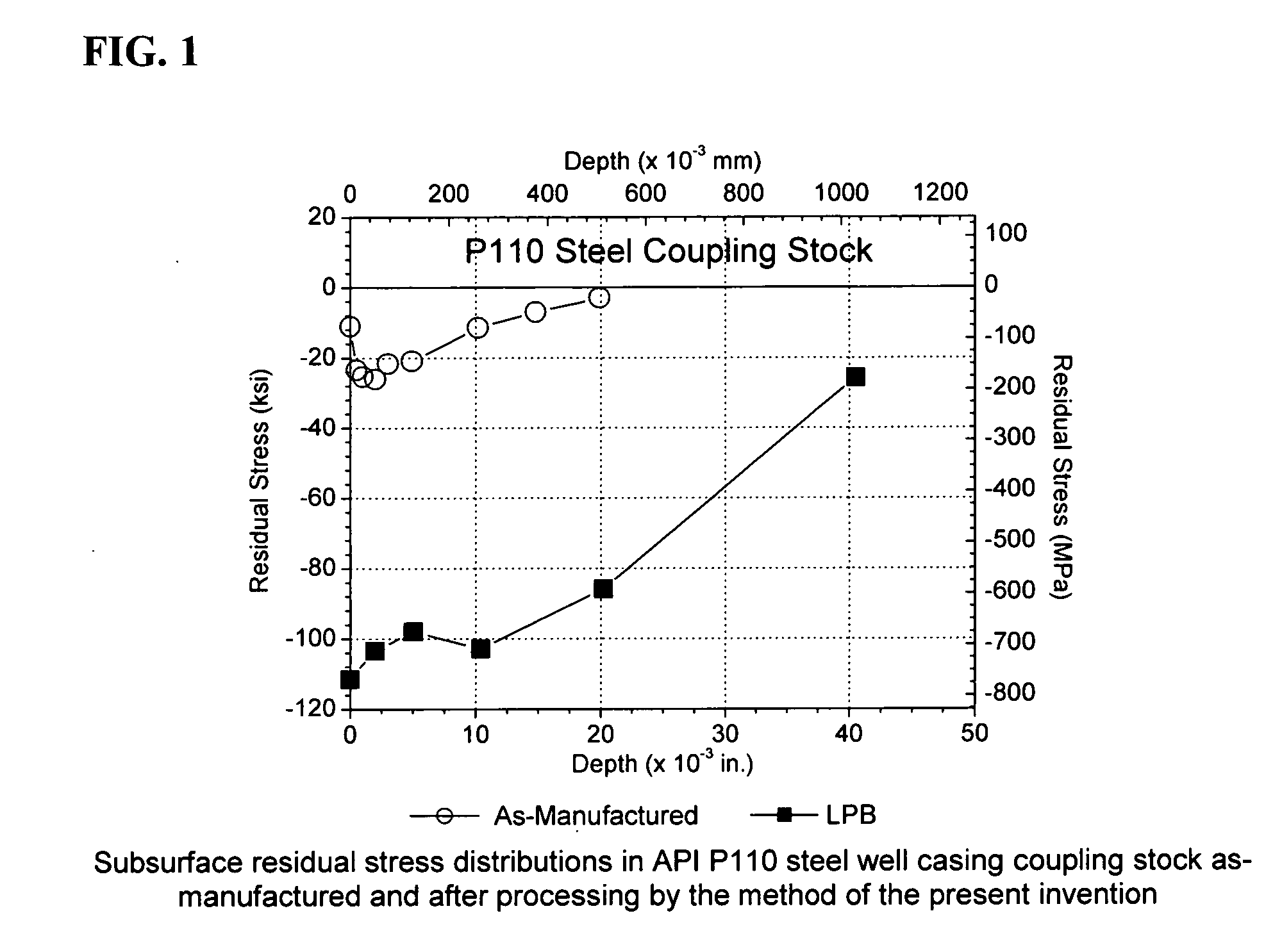
[0034]Referring to FIG. 1, the “as-received” subsurface residual stress distributions created by the current methods of manufacturing components used in a corrosive environment, such as Fuel Recovery Components as well as components used in a wide variety of chemical plant applications (including, but not limited to pipe, tubing, casing and OCTG), is shown in comparison to the beneficial high magnitude deeper compressive residual stress layer created by a preferred method of the current invention. The residual stress is shown in both units of the common engineering usage in the United States, where 1 ksi=1000 psi, and in SI units of MPa. Prior art manufacturing methods used for such typical components, such as OCTG products, provide only relatively shallow compression, generally less than −30×103 psi (−30 ksi or −200 MPa) extending to a depth of only about 0.020 in. (0.5 mm), such as in the example shown. The prior art practice does not attempt to control or optimize in any way the ...


PUM

PropertyMeasurementUnit
depth of compressionaaaaaaaaaa
depthaaaaaaaaaa

Abstract

The present invention relates to a metallic component and method of manufacture of the component for use in a corrosive environment, such as components used in fossil fuel recovery or used in chemical facilities. The components comprise at least one metallic portion having a deep, stable layer of compressive stress for providing life extension and mitigation of fatigue and corrosion related failures. Preferably, the layer of compressive stress has a depth that exceeds the depth of any surface irregularities.

Description

[0001]This application claims the benefit of U.S. Provisional Application No. 61 / 340,282, filed Mar. 15, 2010.BACKGROUND OF THE INVENTION[0002]The present invention relates generally to metallic components used in a corrosive environment, such as components used for fossil fuel recovery that have improved properties and methods of manufacturing such components. More specifically, the present invention are new and novel metallic components for use in corrosive environments such as components used for fossil fuel recovery, and methods of manufacture, whereby the components have improved properties for mitigating or preventing the deleterious effects of stress corrosion cracking (SCC) and fatigue on the useful life of the metallic components. Such components are typically used in recovery and distribution of fossil fuels or used in chemical plant applications.[0003]In the recovery and distribution of fossil fuels and the operation of petrochemical refineries and other types of chemical...

Claims


Application Information

Patent Timeline
Patent Type & Authority Applications(United States)
IPC IPC(8): B22D25/00B21D31/00
CPCB23P9/02C21D7/04Y10T428/12993C21D9/08C21D10/005C21D7/06
Inventor SCHEEL, JEREMY E.HORNBACH, DOUGLAS J.PREVEY, III, PAUL S.
Owner SURFACE TECH HLDG
Learn More