Thin film transistor and method of manufacturing the same
a thin film transistor and film technology, applied in the direction of transistors, semiconductor devices, electrical devices, etc., can solve the problems of low heat resistance, difficult to employ flexible substrates, plastic substrates or film substrates, etc., to prevent hot carrier-induced degradation of tft, small threshold voltage change, and the effect of small threshold voltage chang
- Summary
- Abstract
- Description
- Claims
- Application Information
AI Technical Summary
Benefits of technology
Problems solved by technology
Method used
Image
Examples
example 1
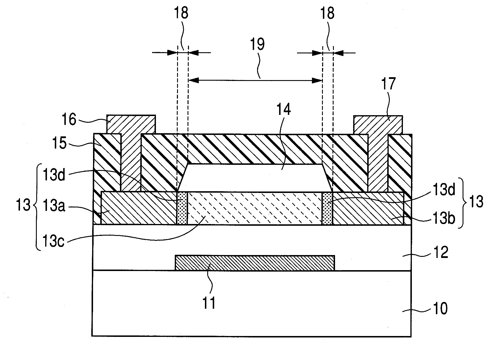
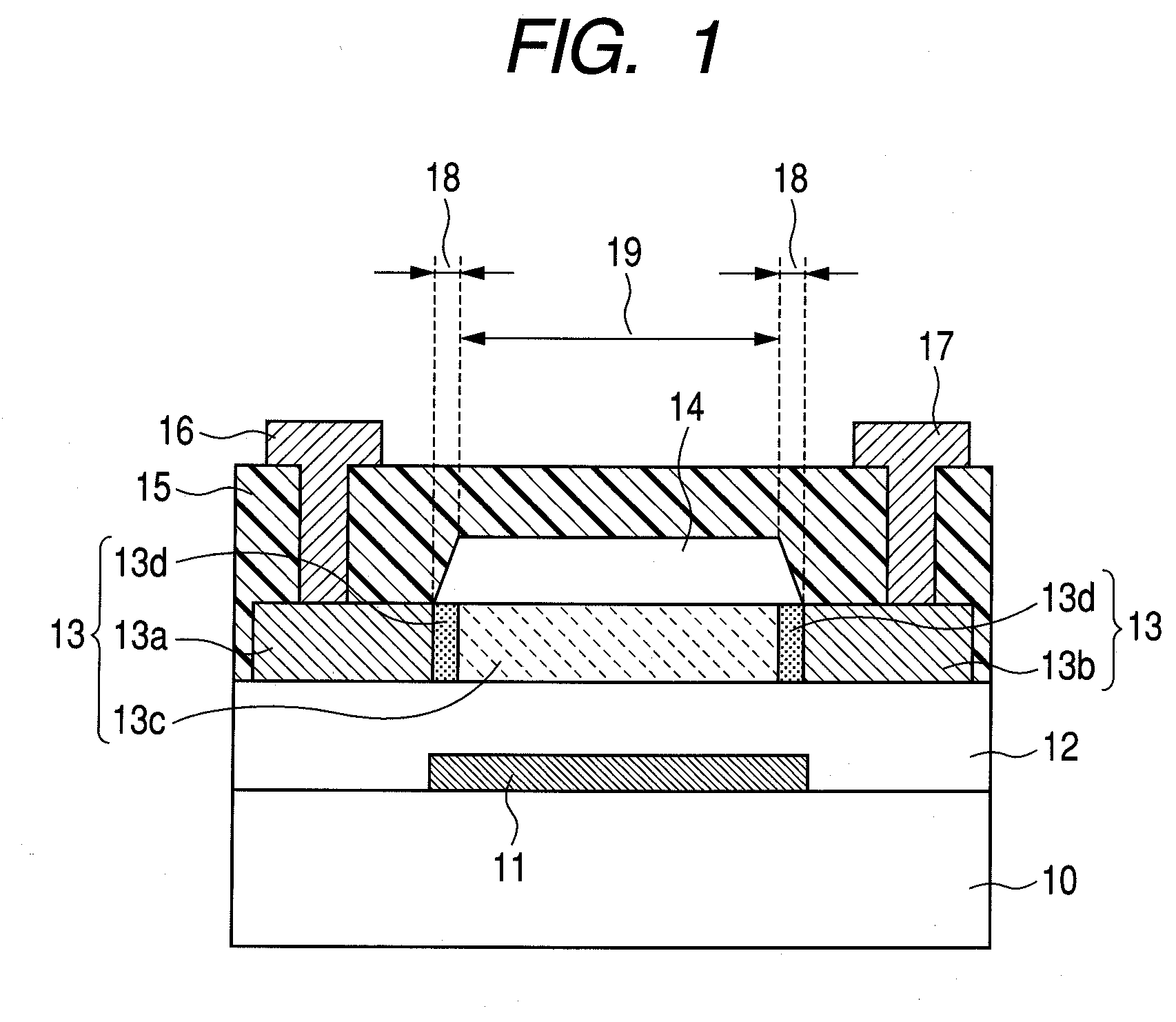
[0081]The bottom gate type coplanar structure oxide semiconductor TFT illustrated in FIG. 1 in which the channel protection layer is a single layer was manufactured in this example.
[0082]First, an electrode layer for forming the gate electrode 11 was formed by the electron beam deposition method on the glass substrate 10 (Corning 1737 manufactured by Corning Incorporated). The electrode material used is Ti / Au / Ti, and the thicknesses of the Ti layer, the Au layer, and the other Ti layer are 5 nm, 40 nm, and 5 nm, respectively.
[0083]After that, the electrode layer was patterned by the photolithography method, thereby obtaining the gate electrode 11.
[0084]A silicon oxide film with a thickness of 200 nm was formed as the gate insulating layer 12 by the sputtering method. In order to form the silicon oxide film, an RF sputtering apparatus was used and the substrate temperature was set to room temperature. A 3-inch diameter SiO2 target was used with the input RF power set to 400 W. During...
example 2
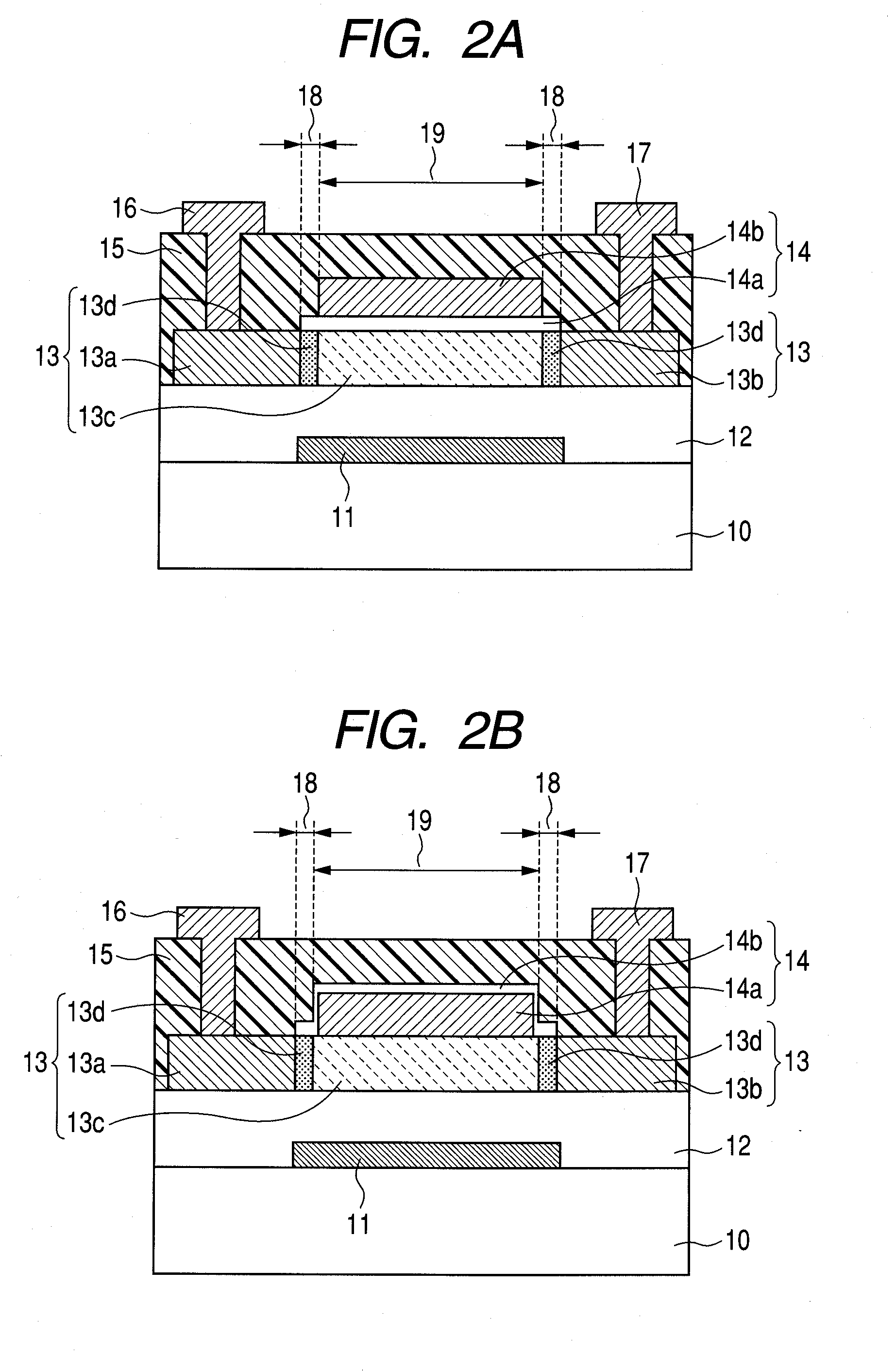
[0094]The bottom gate type coplanar structure oxide semiconductor TFT illustrated in FIG. 2A in which the channel protection layer is formed of two layers was manufactured in this example.
[0095]First, the gate electrode 11, the gate insulating layer 12, and the oxide semiconductor layer 13 are formed on the glass substrate 10 in the same manner as in Example 1.
[0096]On the oxide semiconductor layer 13, a silicon oxide film is formed to have a thickness of 10 nm by the sputtering method as the first channel protection layer 14a. Film formation conditions of the first channel protection layer 14a are the same as those of the channel protection layer 14 of Example 1. The first channel protection layer 14a is then patterned by the photolithography method and the dry etching method.
[0097]A silicon oxide film with a thickness of 300 nm is formed next by the sputtering method as the second channel protection layer 14b. Film formation conditions of the second channel protection layer 14b ar...
example 3
[0102]A display device that uses the bottom gate type coplanar structure oxide semiconductor TFT illustrated in FIG. 8 was manufactured in this example.
[0103]The oxide semiconductor TFT manufacturing steps employed here are the same as those of the above-mentioned Example 1. However, the display device may use any of the oxide semiconductor TFTs illustrated in FIGS. 1, 2A, and 2B. First, a silicon nitride film is formed by the plasma-enhanced CVD method as the insulating layer 128 on the oxide semiconductor TFT 120 of the present invention. A contact hole is formed in the insulating layer 128 by the photolithography method. The electrode 130 is connected to the source wiring line 127 through the insulating layer 128. The electrode 130 is an ITO film formed by the sputtering method. On the electrode 130, the hole transport layer 131a and the light-emitting layer 131b are formed by deposition. α-NPD and Alq3 are used for the hole transport layer 131a and the light-emitting layer 131b,...
PUM
 Abstract
Description
Claims
Application Information
 - R&D
- Intellectual Property
- Life Sciences
- Materials
- Tech Scout
- Unparalleled Data Quality
- Higher Quality Content
- 60% Fewer Hallucinations
Browse by: Latest US Patents, China's latest patents, Technical Efficacy Thesaurus, Application Domain, Technology Topic, Popular Technical Reports.
© 2025 PatSnap. All rights reserved.Legal|Privacy policy|Modern Slavery Act Transparency Statement|Sitemap|About US| Contact US: help@patsnap.com


