Surface-emission laser diode and surface-emission laser array, optical interconnection system, optical communication system, electrophotographic system, and optical disk system
a laser array and laser diode technology, applied in laser cooling arrangements, laser details, electrophotographic systems, etc., can solve the problems of laser diodes showing poor stability in transverse mode, no built-in waveguide structure, and serious deterioration of laser beam quality, etc., to achieve high output power operation, low device resistance, and high speed
- Summary
- Abstract
- Description
- Claims
- Application Information
AI Technical Summary
Benefits of technology
Problems solved by technology
Method used
Image
Examples
example 1
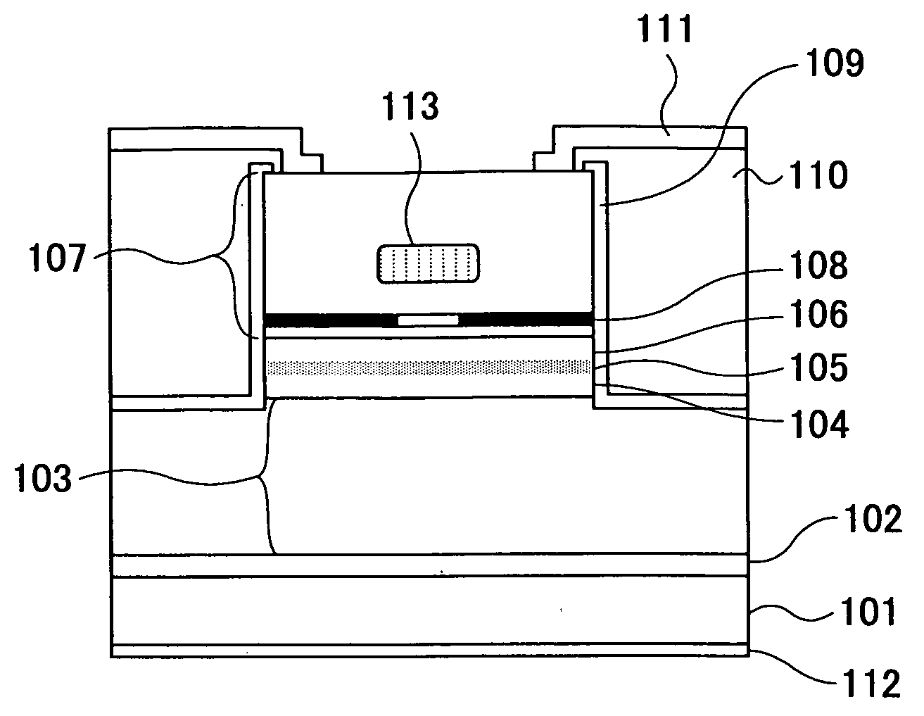
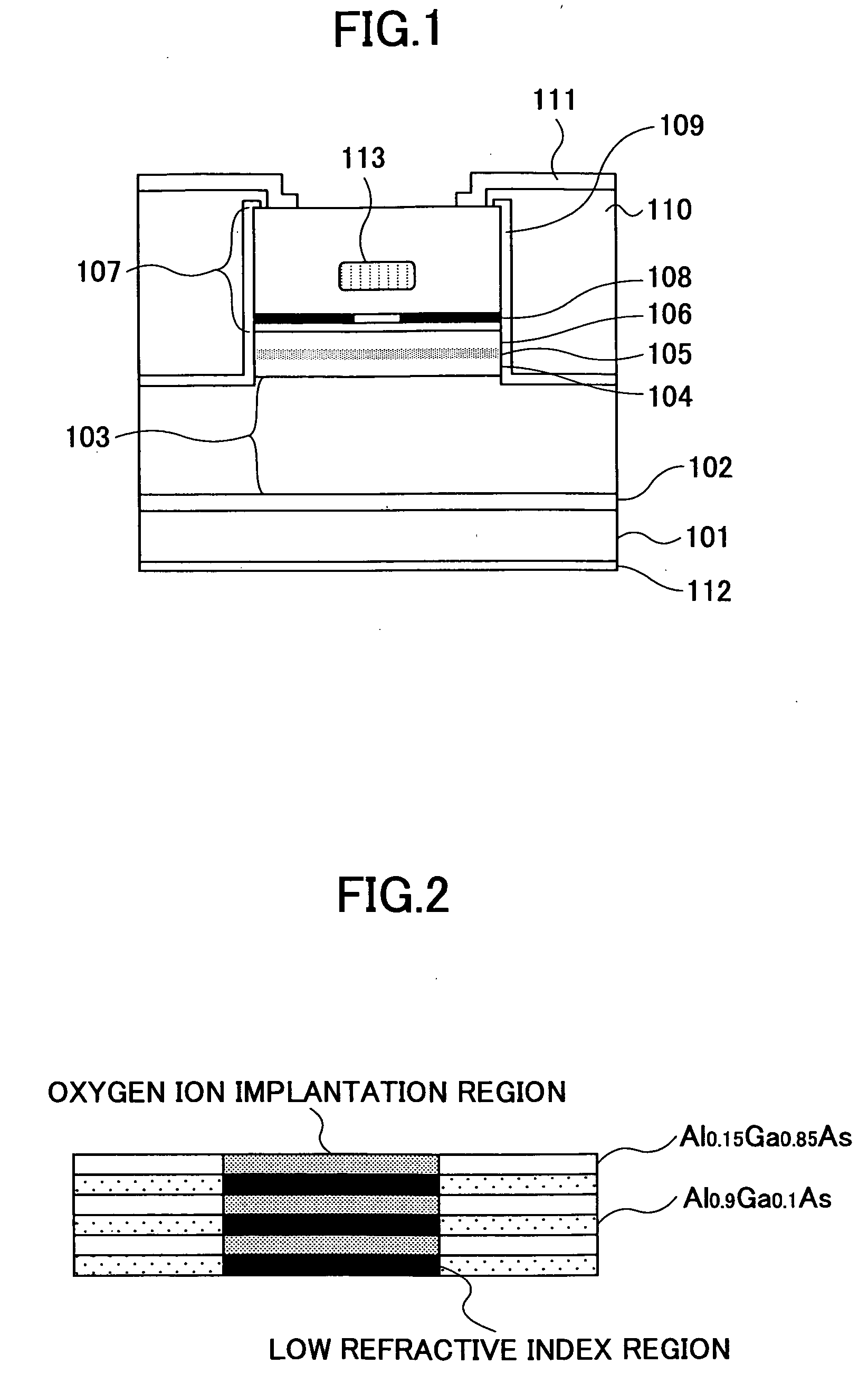
[0356]FIG. 1 shows a surface-emission laser diode according to Example 1 of the present invention, wherein the laser diode of FIG. 1 is a surface-emission laser diode having an active layer formed of a multiple quantum well structure of GaAs / Al0.15Ga0.85As and operating in the 0.85 μm band.
[0357] Hereinafter, the fabrication process of the surface-emission laser diode will be explained according to the fabrication process thereof.
[0358] Referring to FIG. 1, the surface-emission laser diode is based on the layered structure formed by an organic metal chemical vapor deposition (MOCVD) process, wherein the layered structure is formed by using trimethyl aluminum (TMA), trimethyl gallium (TMG) and trimethyl indium (TMI) for the source of the group III elements and by using an arsine (AsH3) gas for the group V source. Further, CBr4 is used for the p-type dopant and H2Se is used for the n-type dopant.
[0359] More specifically, the device of FIG. 1 is constructed on an n-GaAs substrate 10...
example 2
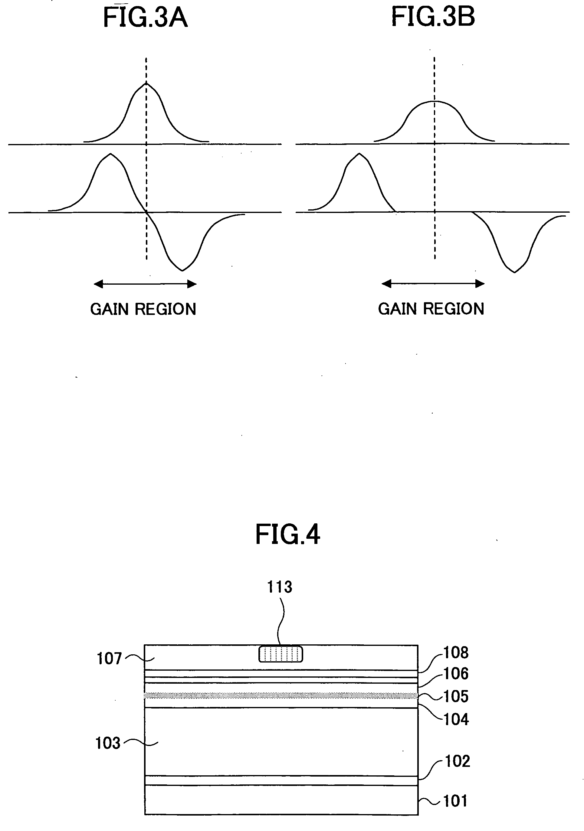
[0377]FIGS. 4 and 5 are diagrams for explaining the surface-emission laser diode according to Example 2 of the present invention.
[0378] Referring to FIG. 4, the laser diode of Example 2 is formed similarly to the laser diode of FIG. 1 up to an intermediate part of the p-type distributed Bragg reflector by a crystal growth process.
[0379] With Example 2, the crystal growth is made up to the foregoing intermediate part of the p-type distributed Bragg reflector, wherein the crystal growth is interrupted in this state and ion implantation of the molecules containing oxygen is conducted to the region that forms the central part of the mesa structure. After the ion implantation process, thermal annealing process is conducted for recovering the crystal defects caused by ion implantation, and the remaining part of the device is formed by conducting a regrowth process.
[0380] As a result of the thermal annealing process conducted for recovering the crystal defect and as a result of the heat...
example 3
[0389]FIG. 6 explains the surface-emission laser diode of Example 3.
[0390] Referring to FIG. 6, it will be noted that the construction of the region surrounding the antiguiding structure 113 in the surface-emission laser diode of FIG. 1 is changed in the case of the device of Example 3.
[0391] In more detail, in the example of FIG. 6, the Al0.9Ga0.1As mixed crystal layer provided for forming the low refractive index layer after the selective oxidation process conducted by ion implantation of the molecules containing oxygen and subsequent thermal annealing process, is grown with increased doping concentration level as compared with the Al0.9Ga0.1As layers used for other regions. The process of device fabrication itself is identical with the case of the device of Example 1.
[0392] It should be noted that a semiconductor material doped to high concentration level shows distinctive optical absorption caused by free carrier absorption. In the case of a p-type semiconductor, in particula...
PUM
 Abstract
Description
Claims
Application Information
 - R&D
- Intellectual Property
- Life Sciences
- Materials
- Tech Scout
- Unparalleled Data Quality
- Higher Quality Content
- 60% Fewer Hallucinations
Browse by: Latest US Patents, China's latest patents, Technical Efficacy Thesaurus, Application Domain, Technology Topic, Popular Technical Reports.
© 2025 PatSnap. All rights reserved.Legal|Privacy policy|Modern Slavery Act Transparency Statement|Sitemap|About US| Contact US: help@patsnap.com


