However, it works with samples (not detected symbols) and samples contain
noise (predominantly quantization
noise).
Therefore, the Symbol-Spaced Feedforward
Equalizer is not so effective in removing the precursor ISI.
The critical issues were that the required performance would include a BER of 1E-7 and that the margin used in theoretical and
simulation studies would be 12dB, while the margin on a measured piece of equipment need only be 6dB.
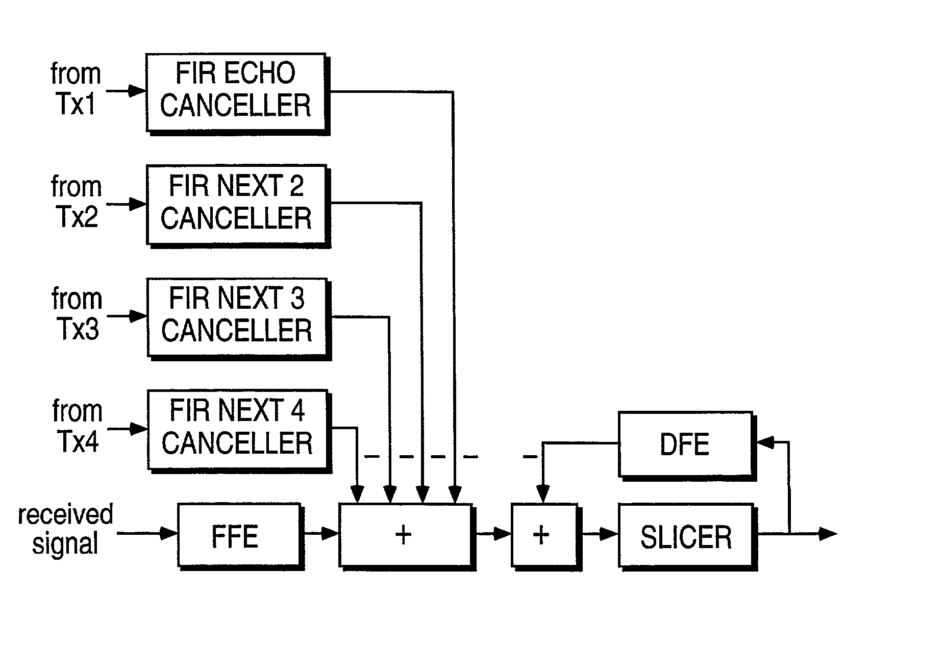
Especially, the Scheme IHE(T / 2) use a Fractionally Spaced FFE to suppress the NEXT's and FEXT's as NEXT and FEXT cancellation is not possible in the environment of xDSL.
However, the basic communications and architectural characteristics of the
bus have not varied from its original release.
Secondly, The stub cables cause little attenuation up to 10MHz.
Fourthly, The presence of stubs has little effect and the main cause of attenuation is believed to be the
bus cable.
Interference (echo and crosstalks) is another major performance-limiting impairments on STP C-17 cables at the high-speed communication.
In many systems, perfect
equalization and interference cancellations are not possible and residual ISI, NEXT's and FEXT's are present at the decision device (slicer).
The problem is that there may be insufficient margin in SNR for the
receiver to operate reliably (at the required threshold BER) on an existing C-17 or Mil-Std 1553 cable
plant.
The critical issues were that the required performance would include a BER of 1E-7 and that the margin used in theoretical and
simulation studies would be 12dB, while the margin on a measured piece of equipment need only be 6dB.
For high speed wireless communication (more than 10 Mb / s),
signal fading and ISI due to the channel
delay spread, are the main factors that significantly degraded the average
bit error rate (BER) performance.
Second, unlike Frequency Division
Multiplex (FDMA) scheme or other frequency hopping multiple access techniques, each transmitted
signal occupies the entire
system bandwidth.
Over
the Internet data communication channels, such as nodes on Small Office or Home Office (SOHO) Networks and Central Offices Switches, there is unpredicted nature in packet-based voice and video
data delivery mechanisms that cause errors that reduce the effective use of the real-time applications such as voice and
multimedia data messages.
Today's cable and wireless communication infrastructures are less than ideal.
There are many instances where the highest achievable data rates are not possible due to the imperfections and defects of the communications medium.
If applications are interactive, a short delay between sender and
receiver is required.
However, if the sender temporarily generates data at a higher rate than the
channel rate, for example during a burst, delay can be experienced at the access point of the network.
On the other hand, a sender may experience blocking when setting up the circuit or the bit-rate of the circuit at the time its capacity may be insufficient for the application bandwidth requests.
In the current Internet networking structure, an unreliable way of IP data deliver such as
packet switching methods is now migrating into the telecom backbone, where there is some QoS policy that applies over the IP data.
Over any type of
communication channel, such as nodes on a private UniNetm wireline network, as illustrated in FIG. 02, there is
distortion that can cause errors in data signaling thereby reducing the effective
throughput.
The imperfections in the
communication channel tend to reduce the resolution of the data bandwidth of the signal being transmitted across the channel.
Furthermore, the data may not be interpreted correctly at the receiving end of the channel if the transmitted signals are outside of a defmed phase and frequency range.
As we show you in the
Gigabit FIG. 26 and FIG. 10, the standard
algorithm has a lot of deficiencies in handling the ISI and Crosstalks.
Even in point to point communication, during heavy network traffic on a typical network, the effective
throughput of the 125 Mbaud network would be reduced in capacity due to the signal ISI
noise, data retries due to lost
data bits and phase lock loss.
Since these loops possess feedback, they suffer from hang up, and thus they tend to have large
acquisition time.
Today's cable and wireless communication infrastructures are less than ideal.
There are many instances where the highest achievable data rates are not possible due to the imperfections and defects of the communications medium.
The imperfections in the communication channel tend to reduce the resolution of the data bandwidth of the signal being transmitted across the channel.
Furthermore, the data may not be interpreted correctly at the receiving end of the channel if the transmitted signal's characteristics are outside of a defined signal's parameter range, as illustrated in FIG. 03.
This is caused by noise, spurious or cross-
coupling problems in the Com2000.TM. reference frequency and phase lock loops, or other frequency generating stages.
PSD measurements are normalized power to a certain bandwidth, usually 1 Hz.
frequency counter measurement techniques are often not accurate or sufficient enough to measure
center frequency.
When a full "period" of the phase interval accumulates, the
data reduction becomes more complicated as proper one-period adjustments must be made to all of the data obtained after the data step.
This error is of interest in determining how far a value is from the actual value.
These changes in the frequency are usually random and are due to the internal oscillator noise.
These random changes in frequency affect the resolution of the measurement just as other
internal noise.
The draw back of a DFE, however, is the error propagation problem.
Because the
tail cancellation signal from the DFE is generated according to the estimated signal, a wrong
estimation of the signal could reduce the chance of correct
estimation of subsequent signals.
In fact, for the channel with severe inter-symbol interference, which can be characterized by a
channel impulse response with a long
tail or a long DFE with significant magnitudes, multiple errors do occur because of the phenomenon of error propagation.
In network communications where the data symbols closely follow each other, specially at multiple of
gigabit speed, time dispersion results in an overlap of successive symbols, an effect known as inter-symbol interference (ISI).
2. Establish a Synchronous Communication Environment via Frequency & Phase
Clock Synchronization during
cold start up mode before the filter's coefficient determination of the
Feed Forward Equalizer (FFE) and Decision Feedback
Equalizer (DFE) are commenced. This a Synchronous Communication Environment initialization's order is used to offset the
clock synchronization
jitter, which degrades the performance of the FFE and DFE equalizers. This is because it creates a transient mismatch between the digital samples of the FFE / DFE
impulse response and the taps of the filter, which can be interpreted as White
Gaussian Noise.
For the Multi-
Gigabit CAT5 application, cross talk, due to the
relative phase of the interfered and interfering signals, is the most significant source of
Steady State noise affecting the receiver's performance.
The second most significant source of steady-state noise is implementation-dependent noise, which is directly related to the variation of the characteristics of the
transmission medium.
This means that the received
baseband signal is complex even though the transmitted
baseband signal before mixing is real.
In the case of two-phase signaling schemes, the
coupling between the two channels further compromises
noise immunity.
Any deviation from the perfect sending
phase offset (X degree relationship) between the two channels results in
cross channel coupling (i.e. one channel "leaking" into the other channel).
In general, the higher the efficiency, in bits per Hz, of the
data signal, the more vulnerable the signal is to the noise and distortion in the channel.
This means that the generation and detection of symbols is more complex than a simple phase detection or amplitude detection device.
Static
Position Error or
Jitter is caused by the error associated with the signal sampling accuracy or the proximity of the timing pulse to the optimum sampling point or to the center of the eye.
Although the resulting variability in delivery delays (itter) and
packet loss do not adversely affect typical Intenet applications--email,
file transfer and Web applications-other applications cannot adapt to inconsistent service levels.
Delivery delays cause problems for applications with real-time requirements, such as those that deliver
multimedia, the most demanding of which are two-way applications like
telephony.
Increasing bandwidth is a necessary first step for accommodating these real-time applications, but it is still not enough to avoid
jitter during traffic bursts.
Even on a relatively unloaded IP network, delivery delays can vary enough to continue to adversely affect real-time applications.
The challenge of these IP QoS technologies is to provide differentiated delivery services for individual flows or aggregates without breaking the Net in the process.
The prospect of such a potentially drastic change makes many of
the Internet's architects very nervous.
This is mainly due to dynamic buffering and that nodes send data into the network at uncontrolled rates.
If the network cannot allocate the requested resources, the sender is either blocked or offered a lower
service quality.
This scheme, as illustrated in FIG. 07 and 02, has the
disadvantage of not handling bursts of data efficiently.
One problem with this scheme is that a
token bucket may release all its tokens at once in one burst.
If several senders do this simultaneously, there is a risk that much data will arrive simultaneously at switch points in the network, as illustrated in FIG. 65.
