Channel equalization system and method

a channel equalization and channel equalization technology, applied in the field of channel equalization system and method, can solve the problems of inflexible data service, difficulty in interoperability and integration of these technologies, and inflexible circuit-switched networks, and achieve the effect of fast connection establishmen

Inactive Publication Date: 2005-06-07
B C LEOW
View PDF24 Cites 409 Cited by
  • Summary
  • Abstract
  • Description
  • Claims
  • Application Information

AI Technical Summary

Benefits of technology

[0020]With this higher SNR margins, the present invention can be used to increase the higher performance and data rate capacity of the channel or to reduce the cost of the channel. For example, increasing the SNR results in simpler Forward Error Correction (FEC) and filtering schemes that reduce the design complexity which leads to power savings and die size reduction. This can be used in higher performance applications such as higher speeds or longer distance. In the higher data rate applications, the enhanced SNR coupled with the multi-channel signal coding can be used to deliver the increased bandwidth. As an example in longer distance or higher speeds for 1000BaseT application, with Com2000™ Speed technology, the new transceiver can deliver 1000 Mb / s over 200 meters vs. 100 meter 802.3ab standard for longer distance applications or 2000 Mb / s vs. 1000 Mb / s standard for higher speed applications respectively. As an example for HDSL2 application, the new transceiver can deliver 1.5 Mb / s over 18 Kft vs. 12 Kft HDSL2 T1 / E1 standard for longer distance applications or 3 Mb / s vs. 1.5 Mb / s standard for higher speed applications.Intellegence (Physical Layer)
[0056]The signal's signature is composed of both the waveform signal itself and the content of the waveforms. The security system transmits the signature of the waveform by pre-positioning the signal at a specific frequency and phase matrix cell. The signal signature of the waveform's content is provided via the pseudo-random noise (PN) signature for each node of the network. The PN auto correlation will be exercised for multi user ID access. This PN signature provides network security by prohibiting any unauthorized intrusion by validating the signature, or E-DNA, of the sending node.

Problems solved by technology

With all of the above technologies, the interoperable and integration of these technologies is difficulty since there is no “Unified” or common architecture that the mentioned communication means can seamlessly be integrated with.
The capacity of the backbone and edge network links has been the main bottleneck in a data and telecommunication system.
Traditionally, circuit-switched networks which are only available for the telecommunication infrastructure, have been too inflexible to provide a data service that is suitable for a wireline data communication and wireless data communication integrated services network.

Method used


Image

  • Channel equalization system and method
  • Channel equalization system and method
  • Channel equalization system and method

Examples


case 1

gnal

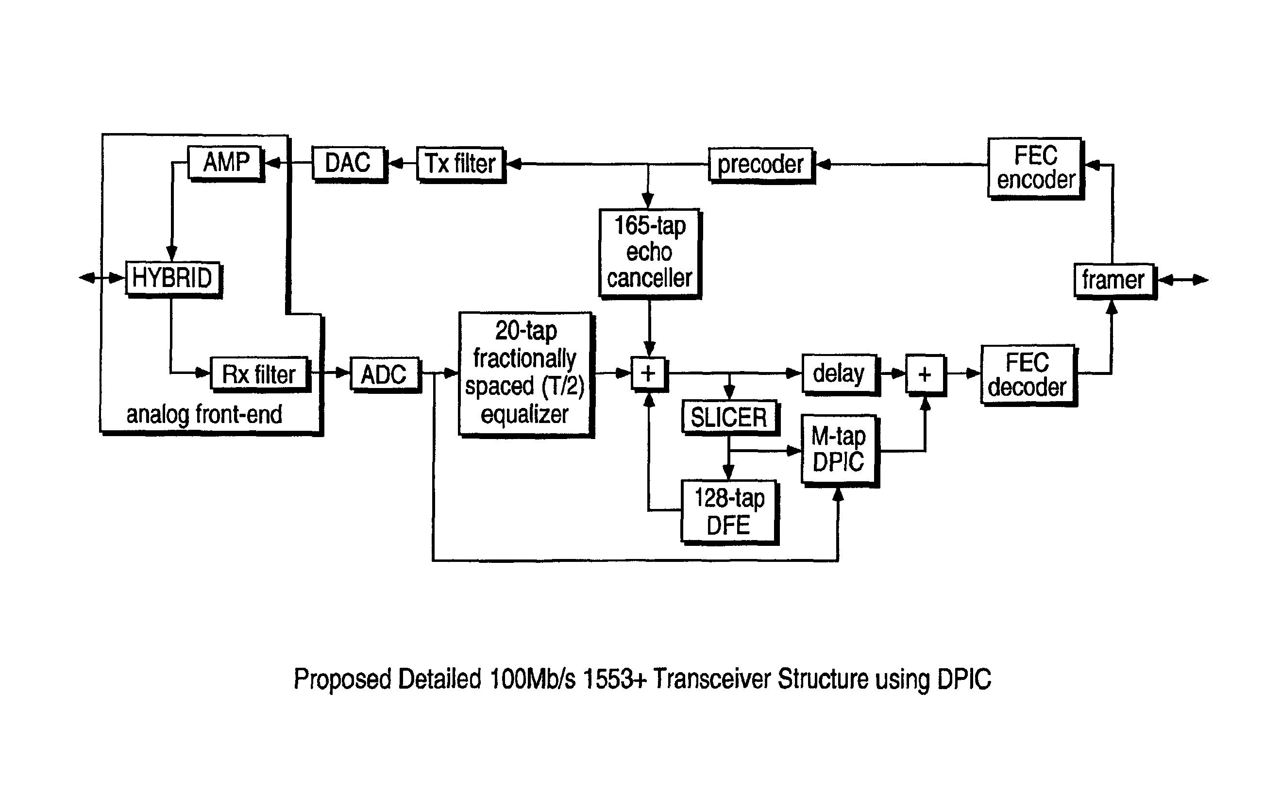
[1653]Suppose that the measured channel plus background noise for the i-th trial is:

C(i)=H+N(i)

where C(i)=[c1(i), c2(i), . . . , cL(i)]T, H=[h1, h2, . . . , hL]T is the sampled (in symbol rate) vector of the channel impulse response, and [.]T denotes the transpose of [.]. Here, we assume perfect time synchronization so that H appears the same regardless of the trial index i. N(i)=[n1(i),n2(i), . . . , nL(i)]T is the noise vector.

[1654]Assuming that the numbers of taps in THP and FFE are NTHP and NFFE, respectively, we construct two NFFE×(L+NFFE−1) matrices, Φc(i) and ΦH, as: ΦC⁢(i)=[c1⁡(i),c2⁡(i),…,cL⁡(i),0,0,…⁢ ,00,c1⁡(i),c2⁡(i),…⁢ ,cL⁡(i),0,…⁢ ,0⋯⋯⋯⋯⋯⋯⋯⋯0,0,…⁢ ,0,c1⁡(i),c2⁡(i),…⁢ ,cL⁡(i)]ΦH=[h1,h2,…⁢ ,hL,0,0,…⁢ ,00,h1,h2,…⁢ ,hL,0,…⁢ ,0⋯⋯⋯⋯⋯⋯⋯⋯0,0,…⁢ ,0,h1,h2,…⁢ ,hL]

[1655]To evaluate the optimum weight coefficients, the correlation matrix of the received samples in the conventional FFE and the correlation vector of the desired symbol with the received samples are required. They...

case 2

gnal

[1659]The following calculation follows a note “Notes on Calculation of QAM DFE” (J. F. Weng, July 1999) which is a little bit different from that used in “DSL Simulation Techniques and Standards Development for Digital Subscriber Line Systems” (W. Y. Chen, 1998) for calculating the optimum weight coefficients in QAM. (Comparison will be done later to see the difference and the effect on performance)

[1660]The calculation can be shown similar to that for PAM signal discussed above while bearing in mind that the signals discussed below for QAM signals are all complex-valued signals.

[1661]Suppose that the measured channel plus background noise for the i-th trial is:

C(i)=H+N(i)

where C(i)=[c1(i), c2(i), . . . , cL(i)]T, H=[h1, h2, . . . , hL]T is the sampled (in symbol rate) vector of the channel impulse response, and [.]T denotes the transpose of [.]. Here, we assume perfect time synchronization so that H appears the same regardless of t. N(i)=[n1(i), n2(i), . . . , nL(i)]T is the n...


PUM


Abstract

A system and method for delivering increases speed, security, and intelligence to wireline and wireless systems. The present invention increases channel capacity by using a parallel or multi-channel structure in such wireless and wireline at the edge or the core of. This new architecture of the present invention uses parallel bitstreams in a flexible way and distributed switching / routing technique, is not only to avoid the potential bottlenet of centralized switches, but also to increase speed with intelligence that is seamlessly integrating into the Fiber Optic Backbone such as WDM and SONET of the MAN / WAN network with a Real-time guarantees, different types of traffic (such as Stringent synchronous, isochronous, and asynchronous data messages) with different demands, and privacy & security of multi access and integrated services environment.

Description

RELATED APPLICATIONS[0001]This application is a divisional of U.S. patent application Ser. No. 09 / 550,395, filed on Apr. 14, 2000, now abandoned, which is a continuation-in-part of U.S. provisional application Ser. No. 60 / 170,455, filed on Dec. 13, 1999.[0002]This application is also a continuation-in-part of U.S. patent application Ser. No. 09 / 444,007, filed on Nov. 19, 1999, now abandoned; which is a continuation-in-part of U.S. patent application Ser. No. 09 / 417,528, filed on Oct. 13, 1999, now issued as U.S. Pat. No. 6,553,085 on Apr. 22, 2003; which is a continuation-in-part of U.S. provisional application Ser. No. 60 / 104,316, filed on Oct. 13, 1998, and which is a continuation-in-part of U.S. provisional application No. 60 / 109,340, filed on Nov. 20, 1998.[0003]This application is also a continuation-in-part of U.S. patent provisional No. 60 / 129,314, filed on Apr. 14, 1999. This application is also a continuation-in-part of PCT application number PCT / US00 / 06842, filed Mar. 15, ...

Claims


Application Information

Patent Timeline
Patent Type & Authority Patents(United States)
IPC IPC(8): H04B3/32H04L1/00H04L25/08H04L25/03H04B3/02H04L7/00H04L25/14H04L1/20H04B1/00H04L25/497H04J3/06
CPCH04B1/00H04L1/0002H04L1/0054H04L1/20H04L1/205H04L5/143H04L5/16H04L7/0008H04L25/03038H04L25/085H04L25/14H04L25/497H04B3/32H04L2025/03509H04J3/0638H04L5/0007H04L2025/03363H04L2025/0349
Inventor TRANS, FRANCOISLE-NGOC, THO
Owner B C LEOW
Why Eureka
Try Eureka