Flash memory structure and its preparation method
A memory unit and flash technology, which is applied in semiconductor/solid-state device manufacturing, semiconductor devices, electric solid-state devices, etc., can solve the problems of poor injection efficiency, difficulty in controlling the size of coupling capacitance, and low programming efficiency, achieving process compatibility, The effect of improving programming injection efficiency and simple preparation method
- Summary
- Abstract
- Description
- Claims
- Application Information
AI Technical Summary
Problems solved by technology
Method used
Image
Examples
Embodiment 1
[0040] Embodiment 1: Flash memory cell with self-aligned split gate floating gate structure based on vertical channel field effect transistor
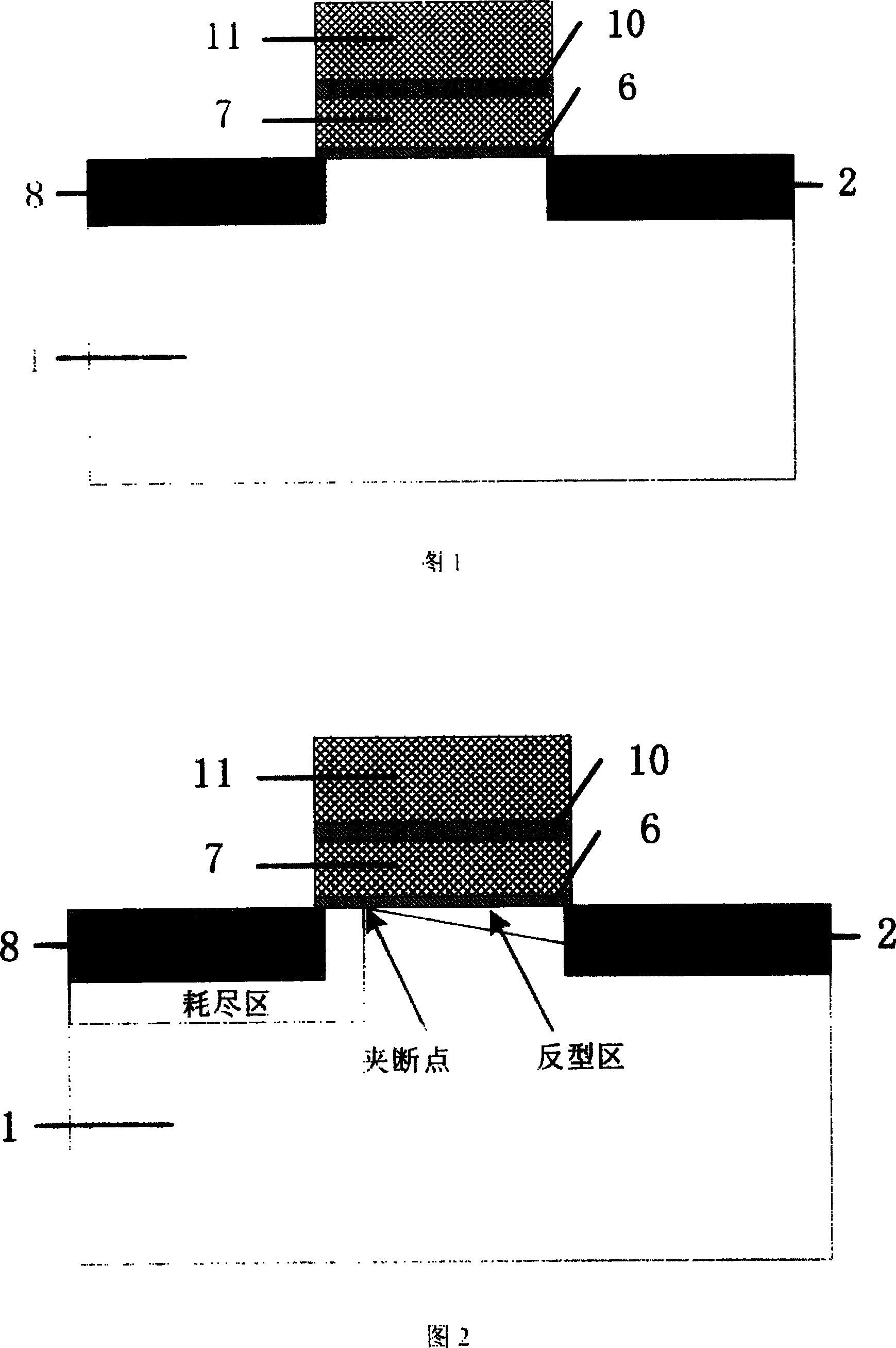
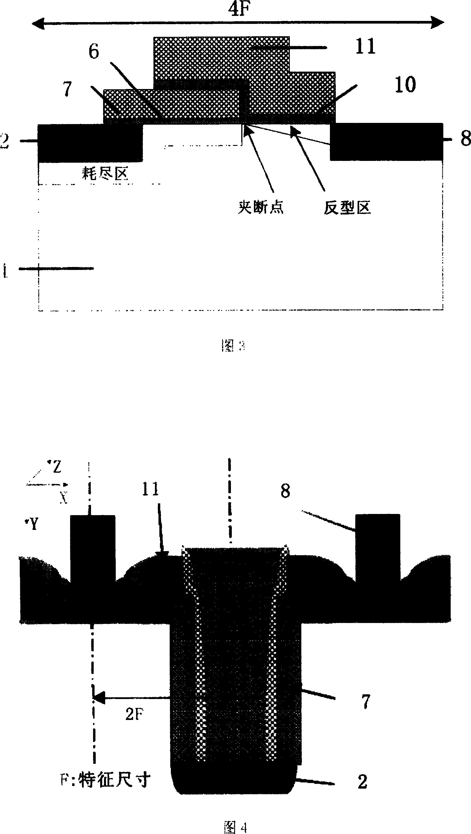
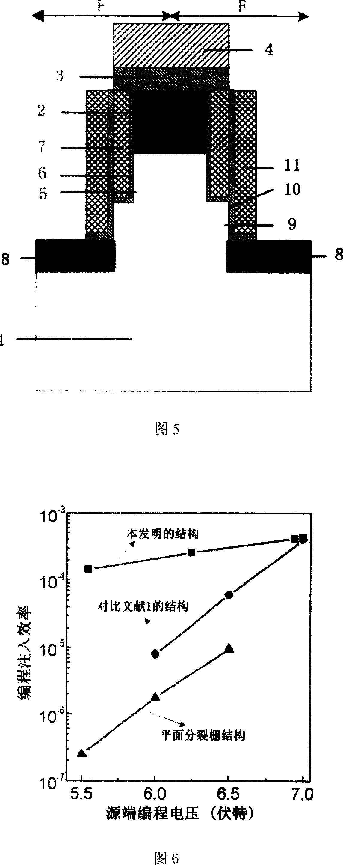
[0041] As shown in Figure 5, it is the flash memory unit of this embodiment, wherein, the silicon substrate 1, that is, the top of the silicon platform is a silicon nitride hard mask 4 and a silicon dioxide hard mask 3, and the n+ above the silicon platform The doped region is the source terminal 2, and its junction depth is 2500 angstroms. Such a deep junction depth is to increase the coupling capacitance between the source terminal and the floating gate to improve programming injection efficiency. The n+ doped regions on both sides of the silicon platform are drain terminals 8, and the junction depth is 1000 angstroms. There are two polysilicon gates on both sides of the silicon platform. The outer polysilicon gate is a control gate 11 with a horizontal thickness of 500 angstroms; the inner polysilicon gate is a floating gate 7 with ...
Embodiment 2
[0044] Embodiment 2: A preparation method of a flash memory unit
[0045] As shown in FIG. 7 , the products of each step shown in FIG. 7 ( 1 )-( 8 ) correspond to each step in a method for preparing the flash memory unit described in the previous embodiment. The method is described in detail below in conjunction with the product of each step:
[0046] (1). Single throwing p-type bulk silicon substrate 1, shallow trench isolation (STI), implanting boron for adjusting the threshold and implanting arsenic for source doping, forming a structure as shown in Figure 7 (1) (the figure only shows The source part, the same below), the source 2 junction depth of the device finally formed is 2500 angstroms;
[0047] (2). Deposit silicon dioxide 300 angstroms and silicon nitride 1200 angstroms, photolithographic device silicon plate, anisotropic etching silicon nitride and silicon dioxide to form double-layer hard masks 3 and 4, as shown in Figure 7 (2) );
[0048] (3). Using ICP with h...
PUM
 Abstract
Description
Claims
Application Information
 - R&D
- Intellectual Property
- Life Sciences
- Materials
- Tech Scout
- Unparalleled Data Quality
- Higher Quality Content
- 60% Fewer Hallucinations
Browse by: Latest US Patents, China's latest patents, Technical Efficacy Thesaurus, Application Domain, Technology Topic, Popular Technical Reports.
© 2025 PatSnap. All rights reserved.Legal|Privacy policy|Modern Slavery Act Transparency Statement|Sitemap|About US| Contact US: help@patsnap.com


