
Electric processing system

a technology of processing system and electric field, applied in the field of electric processing system, can solve the problems of affecting the quality of processing, and affecting so as to avoid reducing the quality of sealing processing and facilitate judgmen

Inactive Publication Date: 2008-04-03
OLYMPUS MEDICAL SYST CORP
View PDF5 Cites 364 Cited by
  • Summary
  • Abstract
  • Description
  • Claims
  • Application Information

AI Technical Summary

Benefits of technology

The present invention provides an electric processing system that can detect and prevent abnormal discharge (sparking) during high-frequency power processing, which can improve the quality of sealing and facilitate the determination of when processing is complete. The system includes bipolar forceps and a drive control apparatus that intermittently applies high-frequency power to the forceps through feedback control. The drive control apparatus can detect abnormal discharge based on the phase difference of current and voltage, reduce the voltage of the high-frequency power, and prolong the application time to prevent damage to the tissue being processed.

Problems solved by technology

Therefore, when a living tissue or the like is held and a high-frequency power is applied, abnormal discharge (a spark) may occur between, e.g., edge parts of the two distal ends even in a state where the living tissue is interposed.
As described above, chattering of an impedance involves a reduction in not only control over application of high-frequency power but also quality of processing, and makes a judgment upon termination of processing difficult.

Method used


Image

  • Electric processing system
  • Electric processing system
  • Electric processing system

Examples


first embodiment

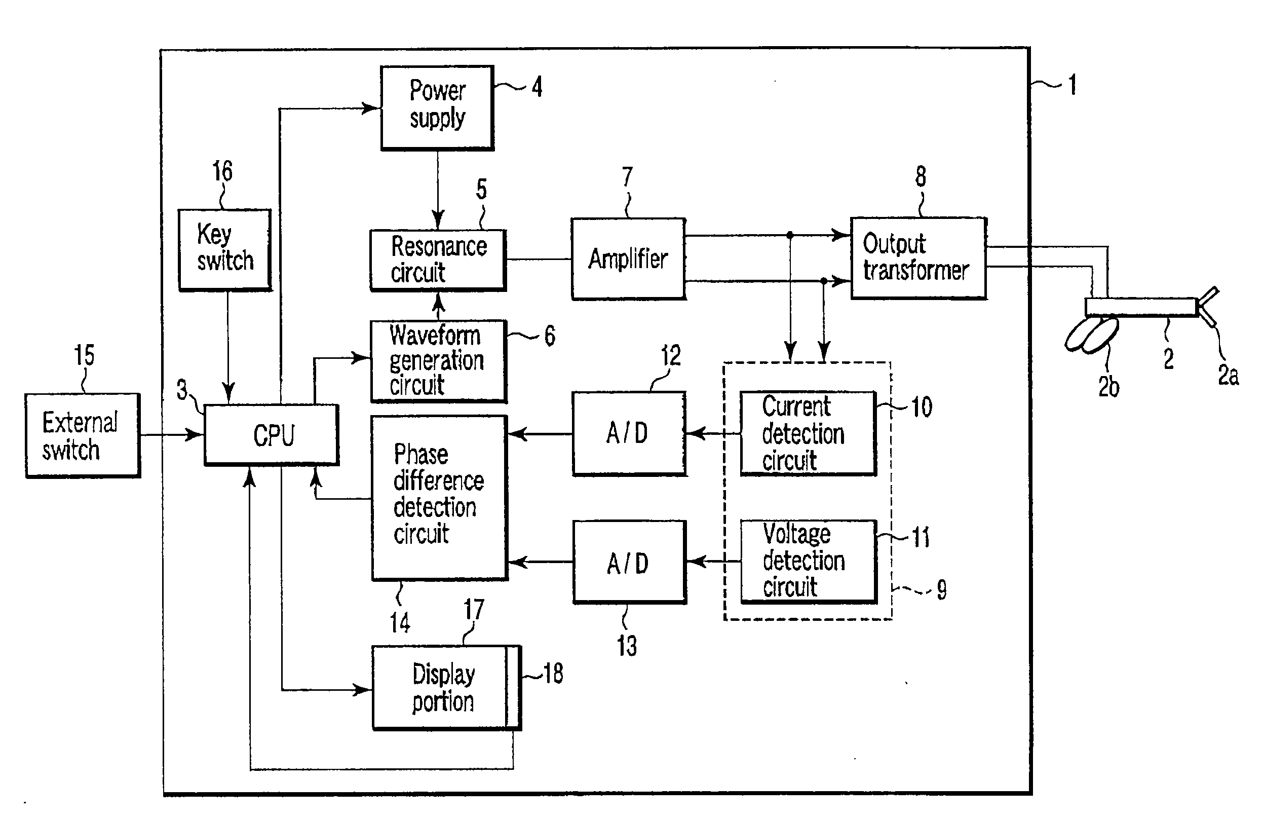
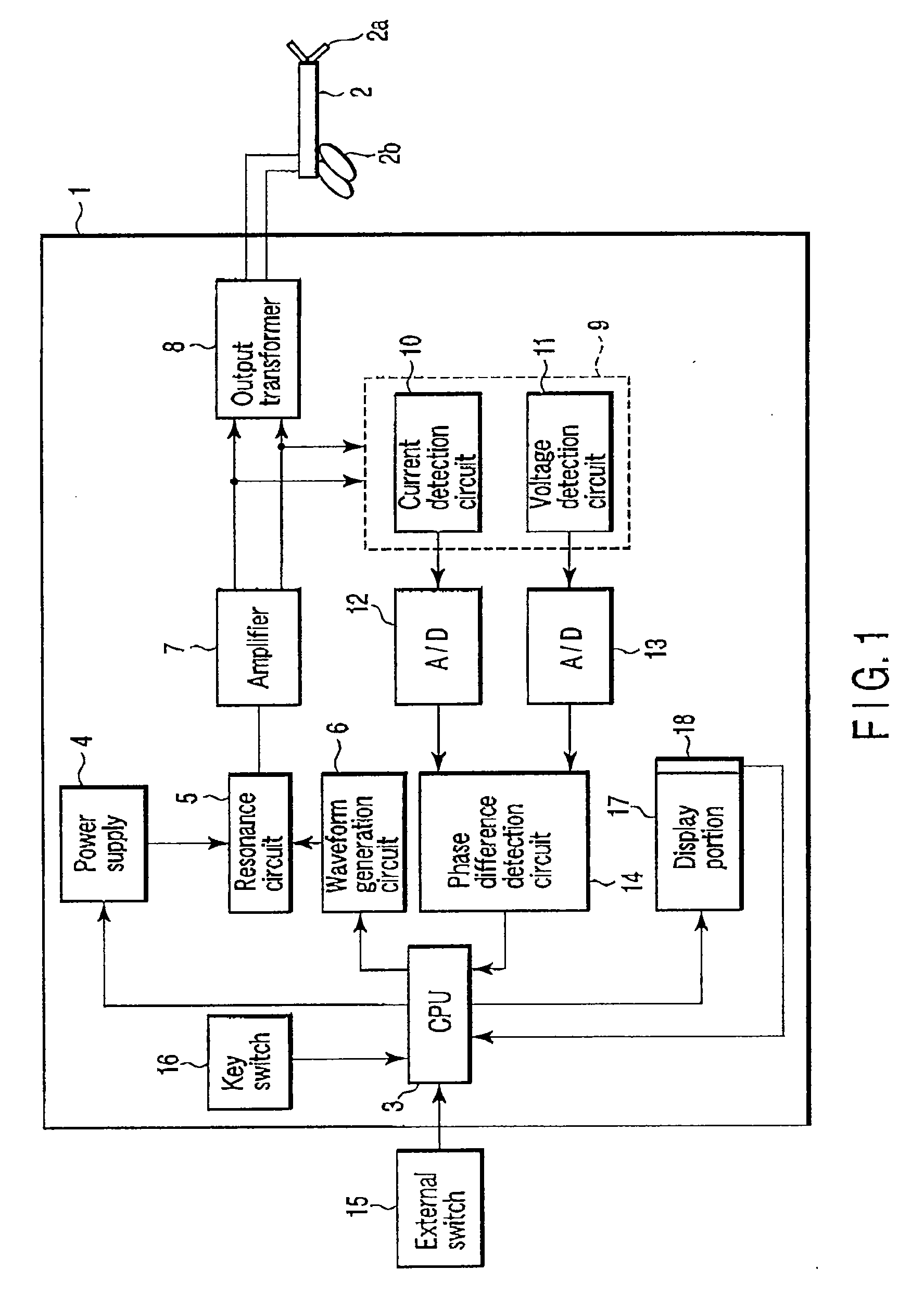
[0019]FIG. 1 shows a configuration of an electric processing system in a first embodiment according to the present invention. Moreover, FIG. 3 is a flowchart illustrating feedback control over a high-frequency power in this embodiment.

[0020]The electric processing system according to this embodiment is roughly constituted of a drive control apparatus main body 1 and an electric processing instrument, e.g., bipolar type sealing forceps 2 which perform welding processing with respect to a blood vessel or the like. Distal ends 2a in which two jaws to which a high-frequency power (a power value: a high-frequency current value×a high-frequency voltage value) can be applied are formed into a double opening or single opening structure are provided at the end of the sealing forceps 2a so that a living tissue or a blood vessel is held to perform processing such as incision, coagulation, sealing, welding or the like. An insulating member such as a ceramic member or a resin member is provided ...

second embodiment

[0035]A second embodiment will now be described.

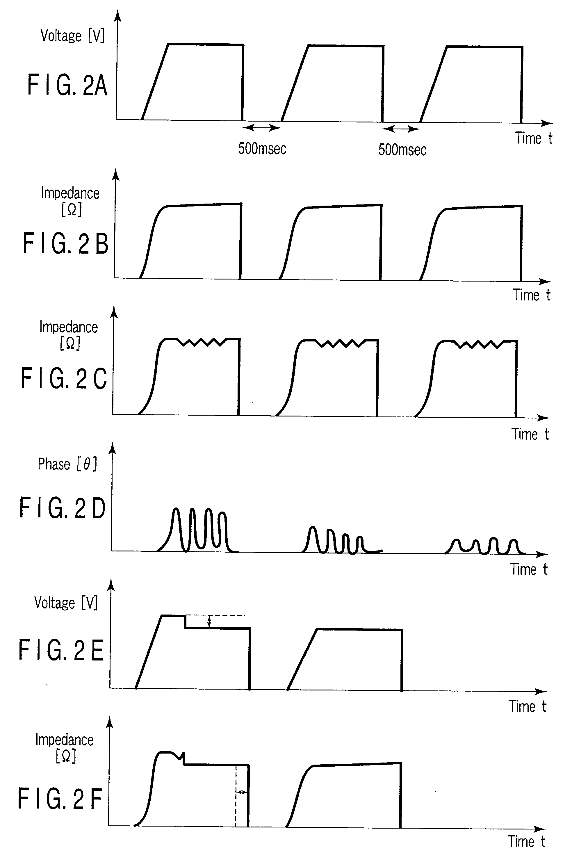
[0036]FIG. 4 shows a configuration of an electric processing system in the second embodiment according to the present invention. FIGS. 5 to 5F are views showing output voltage characteristics and impedance characteristics obtained by the electric processing system according to this embodiment. Moreover, FIG. 6 is a flowchart illustrating feedback control over a high-frequency power in this embodiment. Like reference numbers denote constituent parts in this embodiment which are equivalent to those in the first embodiment, thereby omitting a detailed description thereof.

[0037]The electric processing system according to this embodiment is constituted of a drive control apparatus main body 1 and an electric processing instrument, e.g., bipolar type sealing forceps 2 which perform welding processing with respect to a blood vessel or the like.

[0038]The sealing forceps 2 hold a living tissue or a blood vessel between distal ends 2a to carry o...


PUM


Abstract

There is provided an electric processing system which sequentially monitors a phase difference of intermittently output high-frequency powers in the case of performing feedback control with respect to a high-frequency power applied to bipolar type sealing forceps, reduces the high-frequency power and prolongs an application time at the time of occurrence of abnormal discharge (a spark) at distal ends, thereby terminating the abnormal discharge (extinguishing the spark) to carry out sealing processing.

Description

BACKGROUND OF THE INVENTION[0001]1. Field of the Invention[0002]The present invention relates to an electric processing system which performs a surgical procedure such as coagulation of a living tissue or sealing of a blood vessel for hemostasis by using a high-frequency power.[0003]2. Description of the Related Art[0004]In general, there is known an electric surgical apparatus which uses a high-frequency power to perform a surgical procedure such as incision, coagulation or hemostasis with respect to a living tissue as typified by an electric scalpel. As a similar apparatus, there are known sealing forceps which use a high-frequency power to hermetically close and weld a blood vessel or a fibrovascular bundle. For example, in U.S. Pat. No. 6,033,399 (U.S. patent application Ser. No. 08 / 8,385,458) is proposed a generator for an electric surgical apparatus (an electrosurgical generator) having an output control portion which performs feedback control by monitoring an impedance of a l...

Claims


Application Information

Patent Timeline
Patent Type & Authority Applications(United States)
IPC IPC(8): A61B18/18
CPCA61B18/1206A61B2018/126A61B2018/00345A61B2018/00404A61B2018/00589A61B2018/00619A61B2018/0063A61B2018/00702A61B2018/00726A61B2018/0075A61B2018/00761A61B2018/00779A61B2018/00869A61B2018/00875A61B2018/00886A61B18/1442
Inventor TANAKA, KAZUEIRISAWA, TAKASHIMIHORI, TAKASHI
Owner OLYMPUS MEDICAL SYST CORP
Learn More