
Aqueus electrolytic solution primary battery

a technology of electrolysis solution and primary battery, which is applied in the direction of non-aqueous electrolyte cells, cell components, vent arrangements, etc., can solve the problems of low discharge capacity, large self-discharge, large generation of hydrogen gas, etc., and achieves the effect of improving battery voltage and enhancing the ion conductivity of electroly

Inactive Publication Date: 2007-09-25
KK TOSHIBA
View PDF14 Cites 3 Cited by
  • Summary
  • Abstract
  • Description
  • Claims
  • Application Information

AI Technical Summary

Benefits of technology

[0107]The amount of the additive forming the film may be measured by an electrochemical crystal resonator microbalance method. Further, the effects of the invention may be sufficiently observed if the amount can be confirmed by various spectrochemical methods such as infrared spectroscopy, nuclear magnetic resonance spectrum, and ultraviolet visible absorption spectrum.
[0108]As the solvent, for example, water, methyl ethyl carbonate, γ-butyrolactone may be used.
[0109]It is preferred to further contain halogen ions in the electrolyte. Halogen ions are contained, and thereby the ion conductivity of the electrolyte can be enhanced. As a result, the battery voltage can be improved.
[0110]A compound supplying halogen ions includes, for example, fluorides such as hydrofluoric acid, sodium fluoride, and ammonium fluoride, chlorides such as hydrochloric acid, aluminum chloride, lithium chloride, calcium chloride, and chromium chloride, bromides such as ammonium bromide, zinc bromide, and potassium bromide, and iodides such as ammonium iodide and sodium iodide.
[0111]The concentration of halogen ions in the electrolyte is preferred to be in a range of 0.01 to 6 M / L. If the concentration of halogen ions is less than 0.01 M / L, effects of adding halogen ions may not be obtained sufficiently. If the concentration of halogen ions is more than 6 M / L, the progress of self-discharge tends to increase due to corrosion of the negative electrode. The preferred range is 0.05 to 4 M / L.
[0113]The He gas permeability coefficient at 30° C. of the hydrogen gas permeable sheet is measured by a method disclosed, for example, in JIS K 7126 (1987), which is Method of testing gas transmission rate through plastic film and sheet.

Problems solved by technology

This battery, however, has a problem in reactivity between the aluminum used in the negative electrode and the electrolytic solution, and is hence large in self-discharge, large in generation of hydrogen gas, and small in capacity.
In this aluminum negative electrode battery, however, even if there is no factor for inducing hydrogen gas generation such as an external short-circuit or abnormal high temperature, the negative electrode and electrolysis solution react with each other to generate a huge quantity of hydrogen gas, and a high discharge capacity cannot be obtained.
Aside from the tremendous gas generation during discharge, there is a possibility of electrolyte leakage induced by the osmotic phenomenon caused by dissolution of discharge product of the negative electrode into the electrolysis solution, and it is far from commercial production.
However, the battery disclosed in Jpn. Pat. Appln. KOKAI Publication No. 8-77996 is large in electrolyte leakage, and high discharge capacity cannot be achieved.

Method used


Image

  • Aqueus electrolytic solution primary battery
  • Aqueus electrolytic solution primary battery
  • Aqueus electrolytic solution primary battery

Examples


example 1

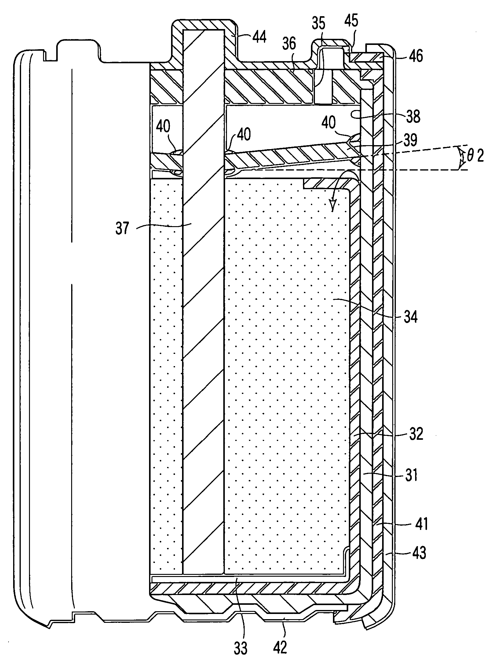
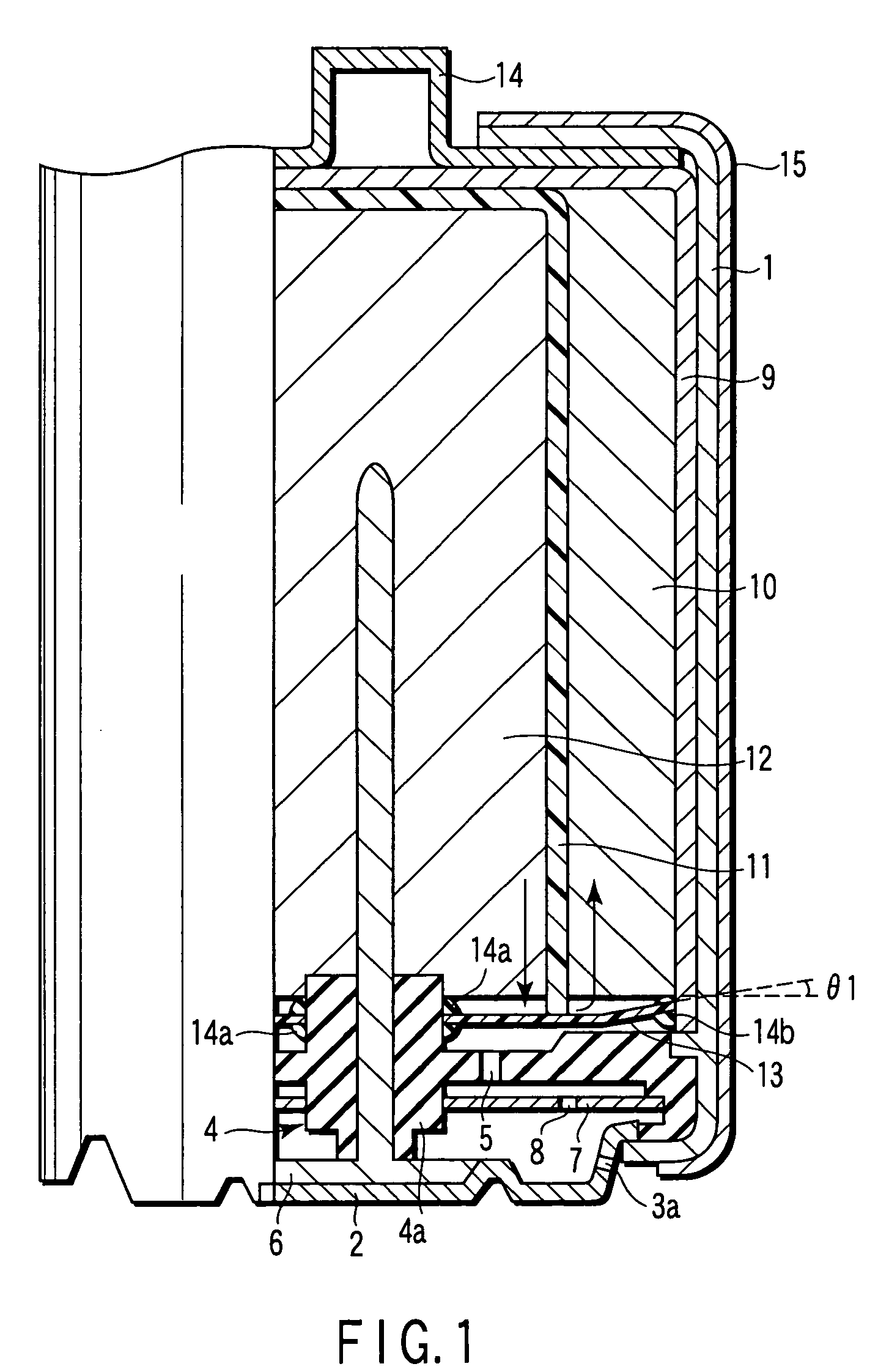
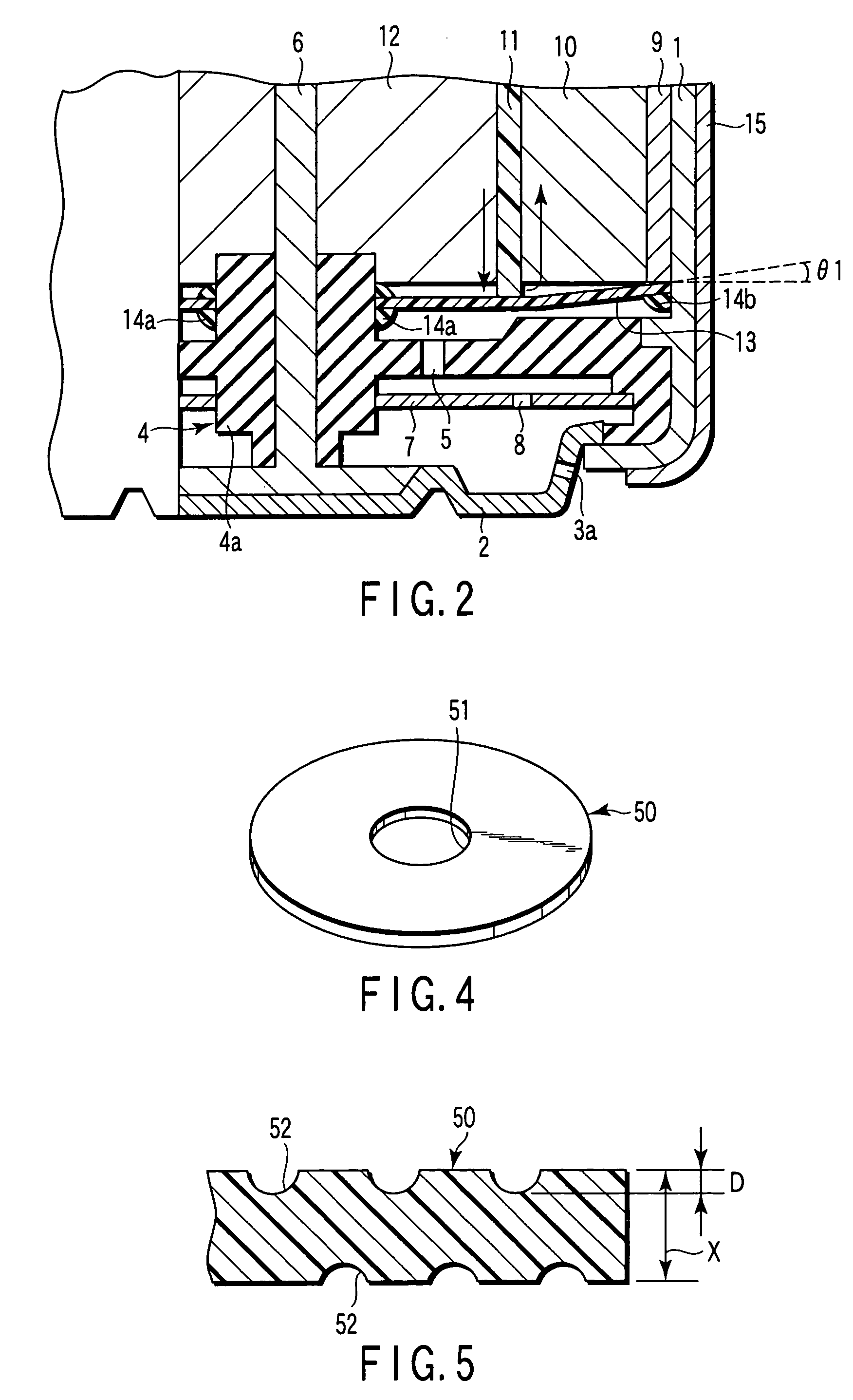
[0158]An aluminum negative electrode battery having an alkaline dry battery structure as shown in FIG. 1 and FIG. 2 was manufactured in the following method.

[0159]

[0160]Electrolytic manganese dioxide (MnO2) was used as positive electrode active material, and this positive electrode active material was mixed with 10 wt. % of acetylene black as conductive agent, and 3 wt. % of polytetrafluoroethylene as binder, and the mixture was molded by pressure into a cylindrical form, and a positive electrode mixture was obtained.

[0161]

[0162]A mixed aqueous solution was prepared, which contains 1 M / L of AlCl3, 0.1 M / L of 2,2-bipyridyl, 0.5 M / L of KCl, and 0.2 M / L of Al(NO3)3.

[0163]

[0164]By mixing 95 wt. % of aluminum powder with purity of 99.99% (4N) and 4 wt. % of acrylic acid polymer as thickener, electrolytic solution was added thereto and a negative electrode gel was prepared. As negative electrode current collector, a stainless steel bar was prepared.

[0165]

[0166]A sheet of ethylene fluoride...

examples 2 to 7

[0170]Aluminum negative electrode batteries in the same structure as in example 1 were manufactured except that the material of the water repellent organic polymer sheet 13, He gas permeability coefficient at 30° C. of the sheet 13, water repellency of the sheet 13, and the negative electrode material were changed as shown in Table 1. In the table, the low density polyethylene has density of 0.91 to 0.93 g / cm3, and high density polyethylene has density of 0.94 to 0.96 g / cm3. As ethylene fluoride propylene copolymer, Teflon FEP (registered trademark) was used.

examples 8 to 14

[0171]Aluminum negative electrode batteries in the same structure as in example 1 were manufactured except that the inclination angle θ1 of the water repellent organic polymer sheet 13 to the positive electrode mixture 10 was changed as shown in Table 1.


PUM

PropertyMeasurementUnit
pressureaaaaaaaaaa
inclination angleaaaaaaaaaa
thicknessaaaaaaaaaa

Abstract

The invention provides a battery including a power generating element container, a positive electrode mixture, and a hydrogen gas permeable sheet provided in an opening of the power generating element container, the hydrogen gas permeable sheet having a water repellence of 2 kPa or more and a He gas permeability at 30° C. in a range of 2×10⁻⁶ to 10000×10−6 (cm3 (STP) cm / sec·cm2·cmHg), wherein a distance between the positive electrode mixture and the hydrogen gas permeable sheet gradually decreases toward a side wall of the power generating element container.

Description

CROSS-REFERENCE TO RELATED APPLICATIONS[0001]This application is based upon and claims the benefit of priority from the prior Japanese Patent Application No. 2002-381375, filed Dec. 27, 2002, the entire contents of which are incorporated herein by reference.BACKGROUND OF THE INVENTION[0002]1. Field of the Invention[0003]The present invention relates to a primary battery such as an aluminum negative electrode battery using at least one of aluminum and aluminum alloy as a negative electrode active material.[0004]2. Description of the Related Art[0005]At present, manganese batteries and alkaline batteries are widely used in portable appliances. Manganese batteries and alkaline batteries both comprise negative electrodes made of zinc and positive electrodes containing manganese dioxide, and have an electromotive force of 1.5 V. Owing to recent developments in portable appliances, primary and secondary batteries of high voltage, large capacity, and light weight are being demanded.[0006]F...

Claims


Application Information

Patent Timeline
Patent Type & Authority Patents(United States)
IPC IPC(8): H01M2/18H01M2/12H01M4/46H01M6/06H01M6/16
CPCH01M2/12H01M2/1264H01M6/168H01M6/16H01M4/46H01M50/30H01M50/394
Inventor SARUWATARI, HIDESATOISHII, HARUCHIKAHIRAI, TAKAHIROTAKAMI, NORIO
Owner KK TOSHIBA
Learn More