
Hot-working die steel, heat treatment method thereof and hot-working die

Pending Publication Date: 2022-05-26
IRONOVATION MATERIALS TECH CO LTD
View PDF0 Cites 1 Cited by
  • Summary
  • Abstract
  • Description
  • Claims
  • Application Information

AI Technical Summary

Benefits of technology

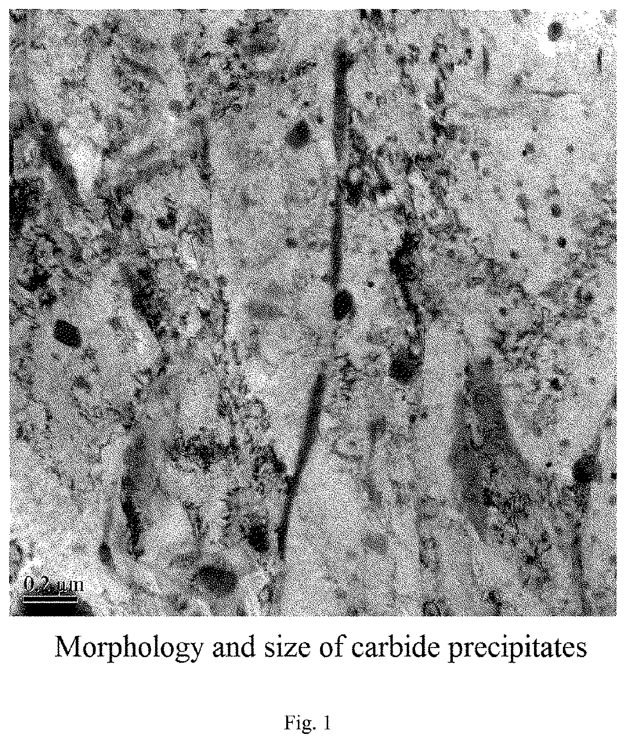
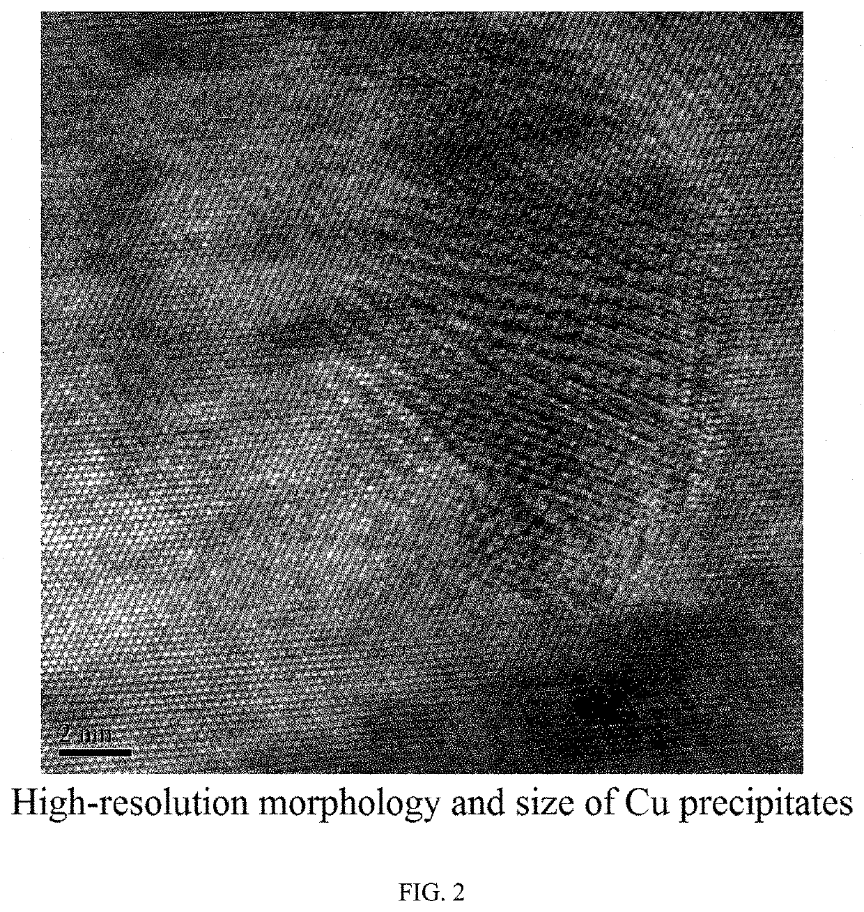
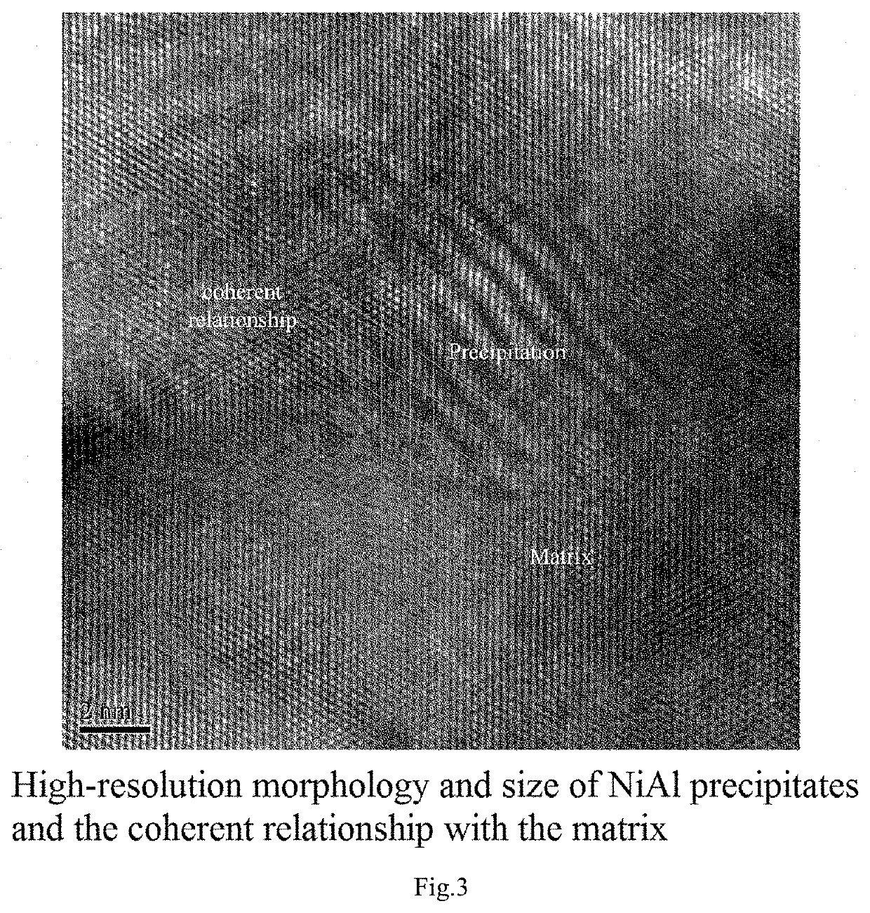
The present invention provides a hot-working die steel with high hardness and thermal conductivity. The material composition is designed to precipitate alloying elements from the matrix in the form of good thermal conductor, resulting in improved thermal conductivity. The hardness of the material is achieved through precipitation strengthening. The size of carbides and precipitates is minimized to achieve high toughness. The heat treatment method simplifies the steps of the heat treatment process for the steel. With the lower carbon content of the steel, coarse primary carbides are unlikely to be generated, and the temperature for solution treatment is reduced, saving energy and reducing production costs.

Problems solved by technology

In recent years, the forming technology of advanced high-strength steel plates for automobiles which can meet both the lightweight and safety requirements of automobiles—hot stamping technology—has posed new requirements and challenges for die steel.
Hot-working die steel used in many manufacturing processes is often subjected to high thermomechanical loads.
These loads usually lead to thermal shock or thermal fatigue.
Thermal shock and thermal fatigue are induced by thermal gradients, the generation of which is because in most production application processes, due to exposure and limited energy of an energy source, the temperature is attenuated to a certain extent and thus heat cannot be transferred stably.
Due to the low thermal conductivity, the thermal expansion difference caused by the temperature difference of the material during service leads to a high chance of forming thermal fatigue cracks in the die and thus a shortened service life of the die.
In addition, the hardness of the carbide precipitated phase which ensures the wear resistance of the die steel is reduced at high temperatures, which leads to the problem of low wear resistance of the die at high temperatures.
Although the thermal conductivity of the tool steel is improved by substituting Cr carbides with Mo, W carbides in that patent, the size of the carbides is not easily controllable.
During the service of the material, large-sized carbides would become sources of fatigue cracks, seriously affecting the fatigue life of the material.
Moreover, large-sized carbides would also seriously deteriorate the toughness of the material.
However, firstly the size of the carbides is not easy to control, and the larger-sized carbides deteriorate the toughness; secondly after adding Ti, liquated TiN and larger-sized TiC tend to be formed, deteriorating the toughness; thirdly, tempering must be performed for multiple times, leading to complex processes; also a secondary hardening peak must be avoided, otherwise the material would have the greatest hardness but the poorest toughness.
The annealing process procedures of patent CN103333997B are complex, taking a long time, but can only solve the problem of element segregation to a certain extent, the size of the larger-sized primary carbides resulted from element segregation cannot be reduced.
Moreover, the module would be seriously oxidized and decarburized if it is annealed at a temperature of above 1000° C. for a long time.
Reducing the precipitation of carbides would inevitably reduce the hardness of the material.
Cr dissolved into the matrix has a serious negative influence on the thermal conductivity of the steel, resulting in the maximum thermal conductivity of the steel not more than 24 W / mK.
Amid increasing pursuit of higher efficiency and shorter cycle time in the production process, H13 is apparently no longer competitive, because its thermal conductivity can no longer be substantially improved.

Method used


Image

  • Hot-working die steel, heat treatment method thereof and hot-working die
  • Hot-working die steel, heat treatment method thereof and hot-working die
  • Hot-working die steel, heat treatment method thereof and hot-working die

Examples


Embodiment Construction

[0049]The technical solution of the present invention will be described below with reference to the embodiments.

[0050]The chemical composition of the steel used for a hot-working die in the present invention comprises by weight percentage: Cu: 2˜8%, Ni: 0.8˜6%, and Al: 0˜3%. In addition to the above components, its alloying composition also comprises: C: 0˜0.2%, Mo: 0˜3%, W: 0˜3%, Nb: 0˜0.2%, Mn≤0.8, Cr≤1.0, and satisfying Ni:Cu≥0.4, Ni:Al≥2, (Mo+W)<6%, Mo:1 / 2 W≥0.5, (Mo+W):2 / 3 C is in the range of 8˜35, the balance of Fe and other alloying elements and impurities. The functions and proportions of the elements in the present invention are as follows.

[0051]Cu: As a good conductor of heat, pure copper has thermal conductivity of 398 W / mK, while pure iron only 80 W / mK. The solubility of Cu is very high in a face-centred cubic phase (austenite), but very low in a body-centred cubic phase (ferrite and martensite), so elemental copper can be sufficiently precipitated in a large amount (as...


PUM

PropertyMeasurementUnit
Temperatureaaaaaaaaaa

Abstract

The present invention relates to a hot-working die steel, a heat treatment method thereof and a hot-working die. Specifically, the present invention discloses a hot-working die steel, its alloying composition comprises, by weight percentage, Cu: 2˜8%, Ni: 0.8˜6%, and Ni:Cu≥0.4, C: 0˜0.2%, Mo: 0˜3%, W: 0˜3%, Nb: 0˜0.2%, Mn: 0˜0.8%, Cr: 0˜1%, the balance of Fe and other alloying elements and impurities. The present invention also discloses a heat treatment method for performing on the hot-working die steel. The present invention further discloses a hot-working die formed of the hot-working die steel underwent through heat treatment according to the heat treatment method.

Description

TECHNICAL FIELD[0001]The present invention relates to a hot-working die steel, a heat treatment method thereof and a hot-working die.BACKGROUND[0002]Hot-working die steel is a type of alloyed tool steel in which chromium, molybdenum, tungsten, vanadium and other alloying elements are added on the basis of carbon tool steel to improve hardenability, toughness, wear resistance and heat resistance. Hot-working die steel is often used for a die for material forming during die casting, forging, and extrusion. In recent years, the forming technology of advanced high-strength steel plates for automobiles which can meet both the lightweight and safety requirements of automobiles—hot stamping technology—has posed new requirements and challenges for die steel. The thermal conduction property of a die is directly related to the resistance to hot cracking, service life and the cycle time in production of the die.[0003]Hot-working die steel used in many manufacturing processes is often subjected...

Claims


Application Information

Patent Timeline
IPC IPC(8): C22C38/48C22C38/42C22C38/44C22C38/06C22C38/04C21D9/00C21D8/00
CPCC22C38/48C22C38/42C22C38/44C21D8/005C22C38/04C21D9/0068C22C38/06C22C38/08C22C38/16C22C38/12C21D1/18B22D17/2209B21D37/01C22C38/20C21D6/001C21D1/26C21D6/02
Inventor YI, HONGLIANGLIU, LIANQIANWANG, GUODONGXIONG, XIAOCHUAN
Owner IRONOVATION MATERIALS TECH CO LTD
Learn More