Inkjet recording medium and inkjet recording method
- Summary
- Abstract
- Description
- Claims
- Application Information
AI Technical Summary
Benefits of technology
Problems solved by technology
Method used
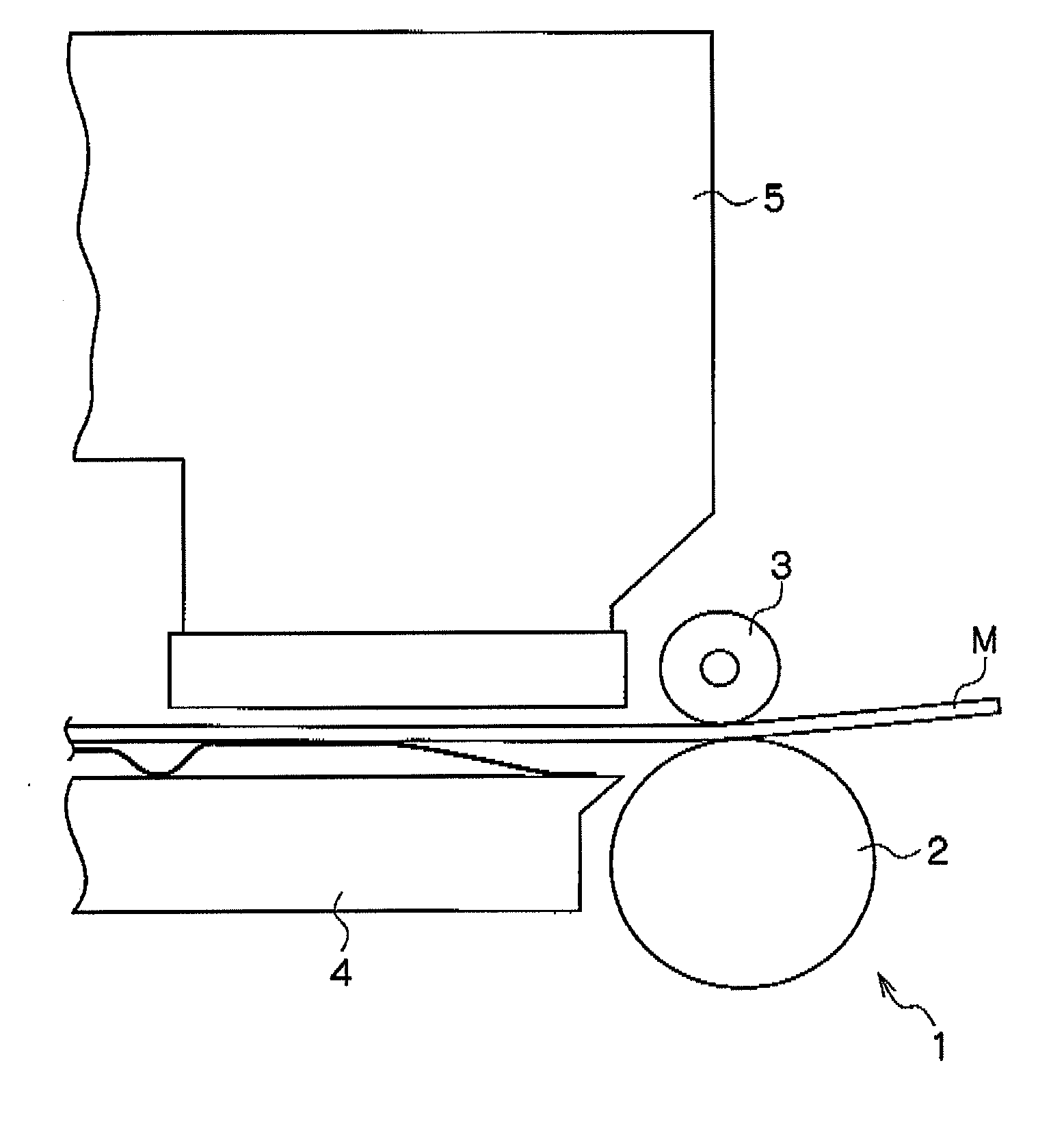
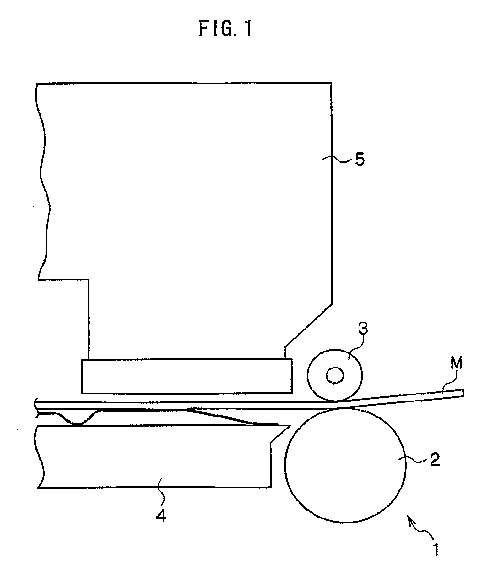
Image

Examples
example 1
Preparation of Support
[0167]50 parts of LBKP made from acacia and 50 parts of LBKP made from aspen were beaten by a disc refiner to have a Canadian Freeness of 300 ml, respectively, thereby forming a pulp slurry.
[0168]Next, to the obtained pulp slurry were added 1.3% of cation-modified starch (CAT0304L (trade name) manufactured by Nippon NSC Ltd.), 0.15% of an anionic polyacrylamide (DA4104 (trade name) manufactured by Seiko PMC Corporation), 0.29% of an alkylketene dimmer (SIZE PINE K (trade name) manufactured by Arakawa Chemical Industries Ltd.), 0.29% of epoxydated behenic acid amide and 0.32% of polyamidepolyamine epichlorohydrin (ARAFIX 100 (trade name) manufactured by Arakawa Chemical Industries Ltd.), with respect to the pulp. Then, 0.12% of a defoaming agent was added thereto.
[0169]Thereafter, the pulp slurry was subjected to paper-making by use of a fourdrinier machine and was dried through a process in which a felt surface of a web was pressed against a drum drier cylinder...
example 2
[0201]An inkjet recording sheet was prepared in a manner similar to Example 1, except that the weight of the base paper was changed to 192 g / m2 and the thickness of the base paper (substrate paper) was changed to 185 μm. The measurement and evaluation were also carried out in a manner similar to Example 1. The results of the measurement and evaluation are shown in Table 1 below.
example 3
[0202]An inkjet recording sheet was prepared in a manner similar to Example 1, except that the weight of the base paper was changed to 182 g / m2 and the thickness of the base paper (substrate paper) was changed to 175 μm, and that the coated amount of the backside coating liquid was changed from 203 ml / m2 to 142 ml / m2. The measurement and evaluation were also carried out in a manner similar to Example 1. The results of the measurement and evaluation are shown in Table 1 below.
PUM
| Property | Measurement | Unit |
|---|---|---|
| Fraction | aaaaa | aaaaa |
| Pressure | aaaaa | aaaaa |
| Current | aaaaa | aaaaa |
Abstract
Description
Claims
Application Information
 - R&D
- Intellectual Property
- Life Sciences
- Materials
- Tech Scout
- Unparalleled Data Quality
- Higher Quality Content
- 60% Fewer Hallucinations
Browse by: Latest US Patents, China's latest patents, Technical Efficacy Thesaurus, Application Domain, Technology Topic, Popular Technical Reports.
© 2025 PatSnap. All rights reserved.Legal|Privacy policy|Modern Slavery Act Transparency Statement|Sitemap|About US| Contact US: help@patsnap.com