
Pvd Coated Substrate

a substrate and coating technology, applied in boring/drilling components, magnetic recording, electrical equipment, etc., can solve the problems of reducing the service life of tools, so as to achieve the effect of increasing the chemical inertness, high hardness, and low friction coefficien

Inactive Publication Date: 2008-10-23
SHEFFIELD HALLAM UNIVERSITY
View PDF9 Cites 29 Cited by
  • Summary
  • Abstract
  • Description
  • Claims
  • Application Information

AI Technical Summary

Benefits of technology

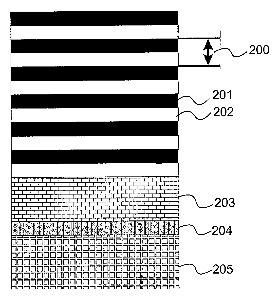
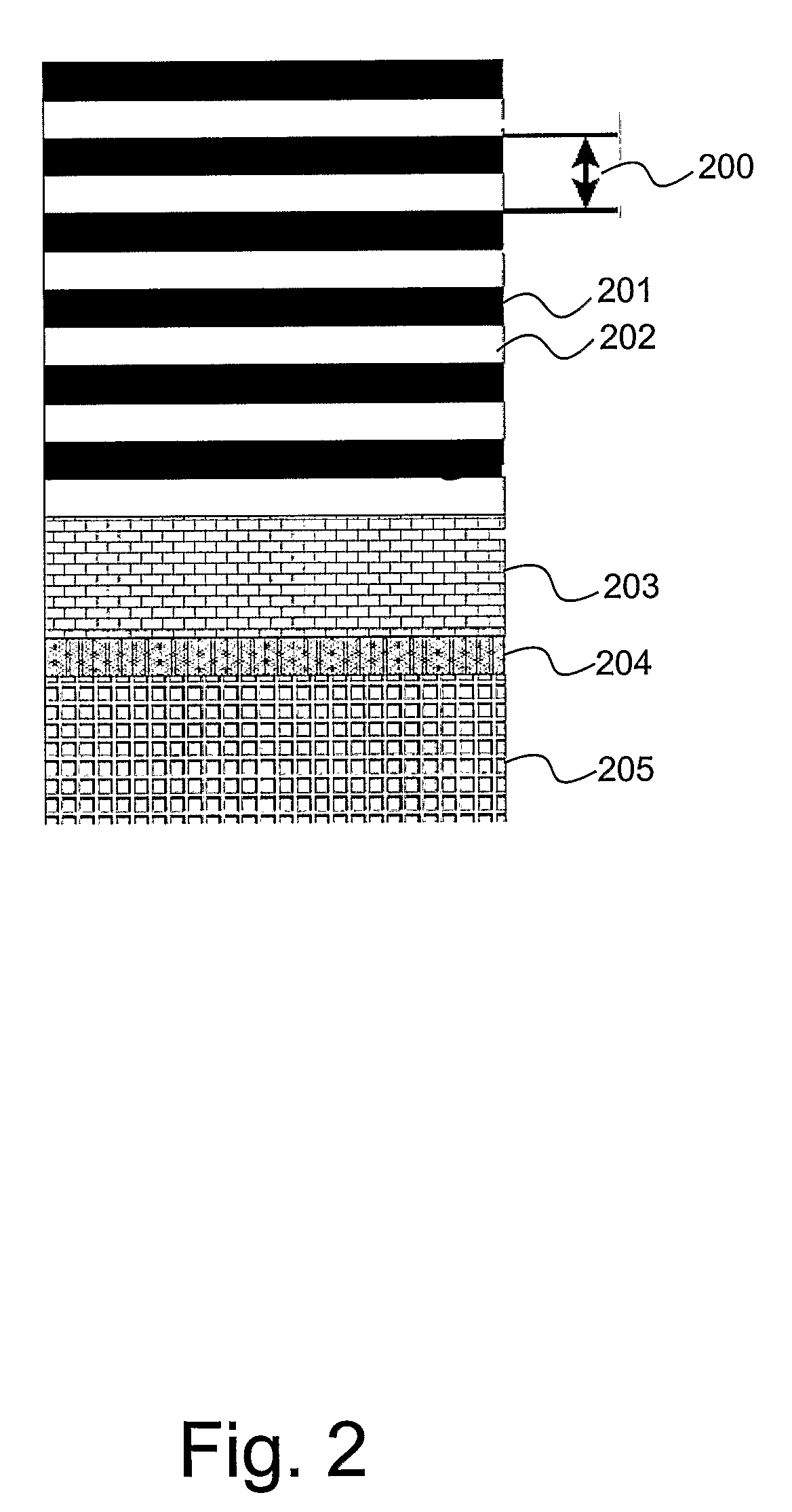
[0016]The inventors provide a PVD coating, and in particular a nanoscale multilayer superlattice PVD coating comprising high hardness, a low friction coefficient and increased chemical inertness.
[0028]In the case of nickel and aluminium based alloys the incorporation of vanadium, and associated reduction in the friction coefficient, is not sufficient to counterbalance the frictional resistance as sliding at the contact interface, (between cutting tool and workpiece material), occurs at the micron level, resulting in material pickup at the cutting edge, termed build-up edge formation. Accordingly, the inventors incorporate an additional component within the coating that has proven to prevent chemical reaction between the coated outer surface of the cutting tool and the workpiece material. This additional component, in the form of carbon serves to further stabilise the friction coefficient thereby increasing the chemical inertness (lower affinity) between cutting tool and workpiece material.
[0032]Important to the performance of coatings, especially in demanding metal cutting applications, is the adhesion to the substrate. Metal ion implantation prior to coating deposition on metal or metal alloy substrates has been shown to promote localised epitaxial growth and improve adhesion of even highly stressed super-hard nano scale compositionally modulated coating systems. The high power impulse magnetron sputtering (HIPIMS) discharge is a relatively newly developed PVD technique which allows high plasma density and ionised metal particles to be produced at low pressures and without macro particle generation.
[0033]Bombarding the substrate surface with metal and / or gas ions has proved to be particularly successful. Excellent bonding strengths between coating and substrate are achieved due to the promotion of local epitaxial growth of the coating on the steel or tungsten carbide substrate. When the metal and / or gas ions are produced by a conventional cathodic arc discharge, an undesirable effect of droplet generation occurs which causes enlarged growth defects during the coating process. HIPIMS utilises pulsed magnetron discharges with extremely high power densities—up to three orders of magnitude higher than conventional systems. According to the present invention, the HIPIMS discharge is distributed over practically the entire cathode area providing a smooth erosion profile on the target and avoiding melting or droplet generation during the pretreatment prior to coating thus ensuring enhanced coating-substrate adhesion and high coating microstructural integrity. This in turn provides a coating with extremely high wear and corrosion resistance. The HIPIMS technique utilised with the present invention is disclosed in Surface and Coatings Technology 163-164 (2003) 267-272.
[0036]According to the present invention the HIPIMS discharge operation parameters may take any value as will be appreciated by those skilled in the art in order to bombard the substrate surface with accelerated metal ions (e.g. Cr+Nb+, V+ or Ti+) to clean the surface so as to provide metal ion implantation and promote epitaxial growth, resulting in high adhesion and high microstructural integrity of the coating.

Problems solved by technology

For example, highly used carbon-based composite, workpiece materials laminated with aluminum alloy sheeting, are so abrasive that unprotected, standard cutting tools are capable of cutting a relatively small portion only of the workpiece material.
This is further complicated by the orientation of the top and bottom layers when “through” drilling the composite materials.
The cutting edges of such tools are blunted very rapidly after, for example only two drilling operations, whereby the tool is no longer suitable for use and must be discarded.
Both these types of alloy exhibit low thermal conductivity resulting in intensive heat generation at the cutting region.
Consequently, it is a common problem for the geometry of the cutting tool to alter, following only small or moderate periods of cutting of these types of alloy, thereby deteriorating the cutting performance.
However, such coatings whilst addressing the problems of wear resistance are still susceptible to micro welding and workpiece material pick-up due to the intensified chemical interaction between the coating and the workpiece material resulting from friction and hence heat generation at the tool-workpiece interface.

Method used


Image

  • Pvd Coated Substrate
  • Pvd Coated Substrate
  • Pvd Coated Substrate

Examples


example 1

Nanoscale Superlattice Multilayer Coating

[0052]A deposition procedure for the production of a nanoscale, compositionally modulated, multilayer structured coating of (VMe)(CN) / (MeV)(CN), where Me is AlTi is described.

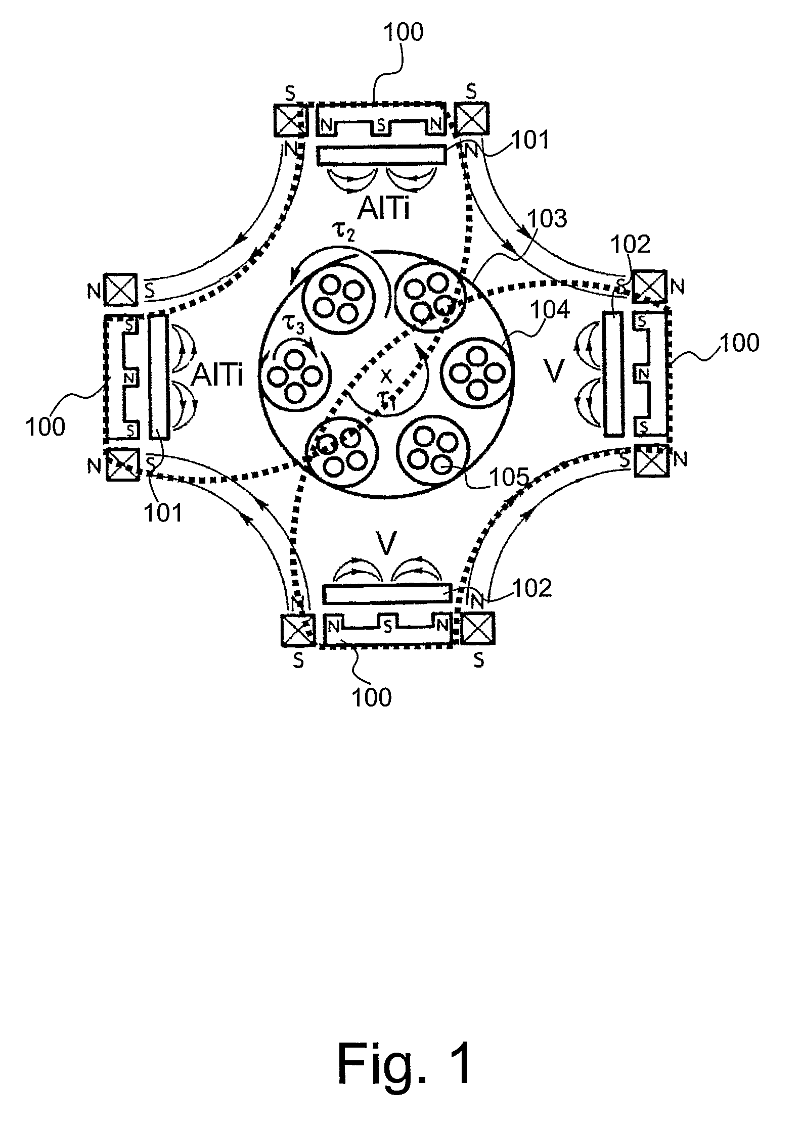
[0053]The (VAITi)(CN) / (AITiV)(CN) superlattice nanoscale multilayer coating is deposited by reactive sputtering of two pairs of AlTi 50:50 at. % and V 99.8% pure targets opposing each other in a common Ar+N2+CH4 atmosphere as illustrated in FIG. 1 herein.

[0054]The necessary carbon atoms can be supplied by other carbon containing reactive gasses such as C2H2 or by evaporation or sputtering of a solid graphite target.

[0055]The metal atoms in the film can be produced not only by various types of sputtering techniques but also by evaporation methods such as arc evaporation.

[0056]The nanoscale multilayer coating deposition process utilized in this example comprised three major steps: surface pretreatment (etching), base layer deposition and nanoscale multilayer deposition.

[00...


PUM

PropertyMeasurementUnit
thicknessaaaaaaaaaa
thicknessaaaaaaaaaa
thicknessaaaaaaaaaa

Abstract

A PVD coating is disclosed, and in particular a nanoscale multilayer superlattice PVD coating comprising high hardness, a low friction coefficient and increased chemical inertness. The multilayer coating comprises a repeating bilayer represented by (VxMe(i-x))CyN(i-y) / (MezV(1-z))CyN(i-y) where 0.1≦x≦0.9; 0.01<y<0.99 and 0.1≦z≦0.9 and Me is a substantially pure metal or a metal alloy. The composition of the coating through the layers alternates from layer to layer according to a V-rich layer and a Me-rich layer modulated sequence. Vanadium is incorporated within the layer composition and has been found to act as a lubricating agent during sliding wear. Carbon, also incorporated within the coating, serves to further stabilise the friction coefficient thereby increasing the chemical inertness between cutting tool and workpiece material.

Description

FIELD OF THE INVENTION[0001]The present invention relates to a coating for a substrate and, in particular although not exclusively, to a coating for a cutting tool exhibiting high hardness, low friction and increased chemical inertness.BACKGROUND TO THE INVENTION[0002]There is a continued increase in the requirement for highly durable cutting tools in response to the demand for and manufacture of more exotic, sophisticated high strength, structural materials used particularly within the aerospace and automotive industries. These materials bring substantial benefits to these industries due to their very high strength to low weight ratio.[0003]For example, highly used carbon-based composite, workpiece materials laminated with aluminum alloy sheeting, are so abrasive that unprotected, standard cutting tools are capable of cutting a relatively small portion only of the workpiece material. Being dependent upon the composition of the laminates, the cutting process has to cope with differe...

Claims


Application Information

Patent Timeline
Patent Type & Authority Applications(United States)
IPC IPC(8): B23B27/14B32B15/00B32B5/00C23C28/02C23C14/22C23C14/00
CPCC23C30/00H01J37/3467C23C28/42Y10T428/265Y10T428/24975Y10T407/27Y10T408/78C23C28/044Y10T428/31678C23C14/0664
Inventor HOVSEPIAN, PAPKENEHIASARIAN, ARUTIUN P.
Owner SHEFFIELD HALLAM UNIVERSITY
Learn More