Method for particulate introduction for metal furnaces
a metal furnace and particulate technology, applied in the direction of furnaces, manufacturing converters, lighting and heating apparatus, etc., can solve the problems of reducing the efficiency of use, limiting the amount of energy which can be introduced into the furnace and the rate at which it can be used efficiently, and a flashback of the flame against the side wall where the burner is mounted
- Summary
- Abstract
- Description
- Claims
- Application Information
AI Technical Summary
Benefits of technology
Problems solved by technology
Method used
Image
Examples
first embodiment
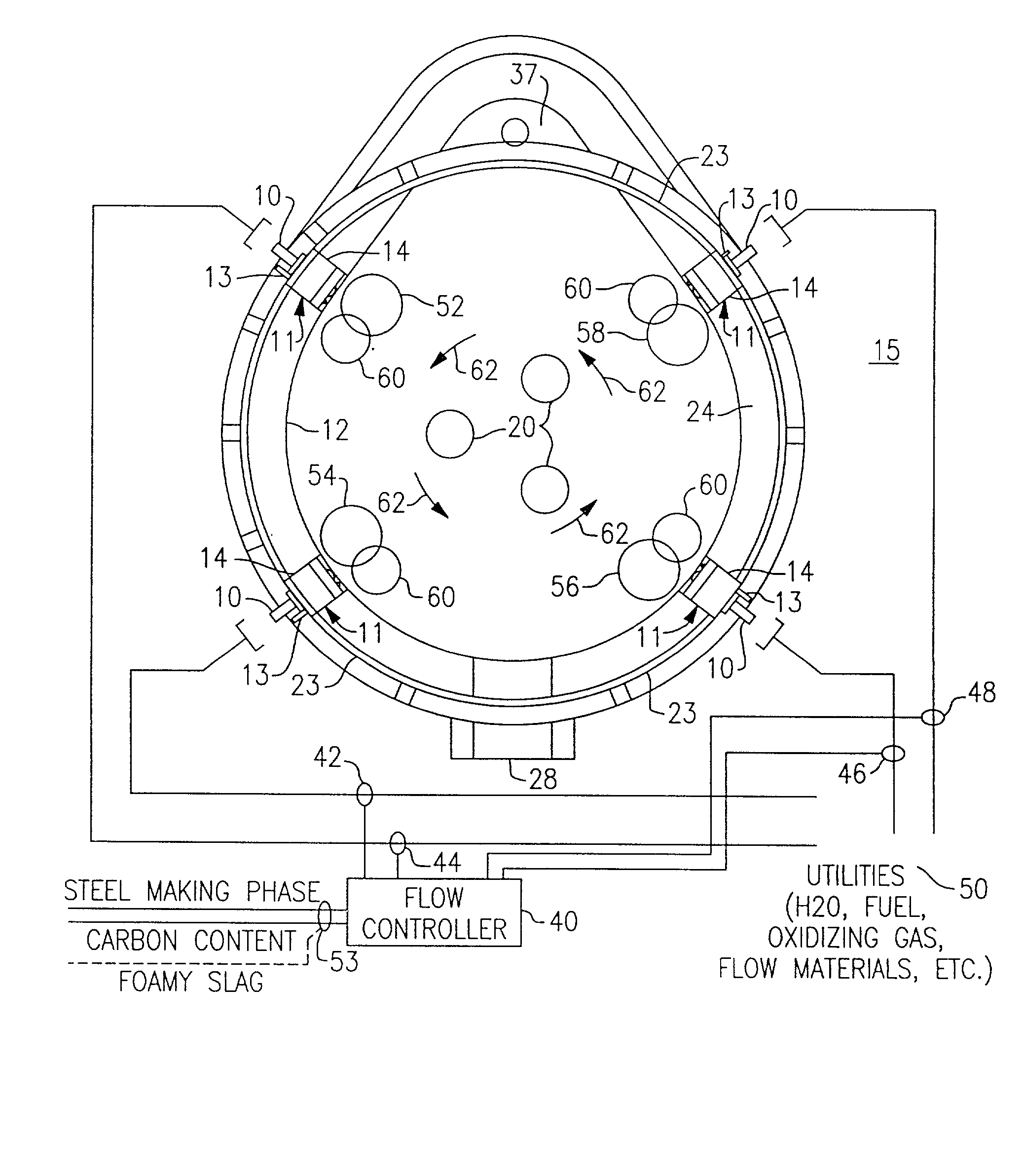
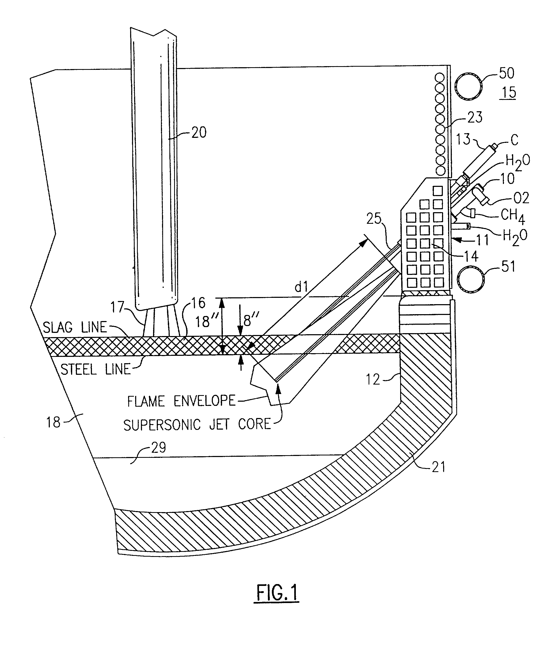
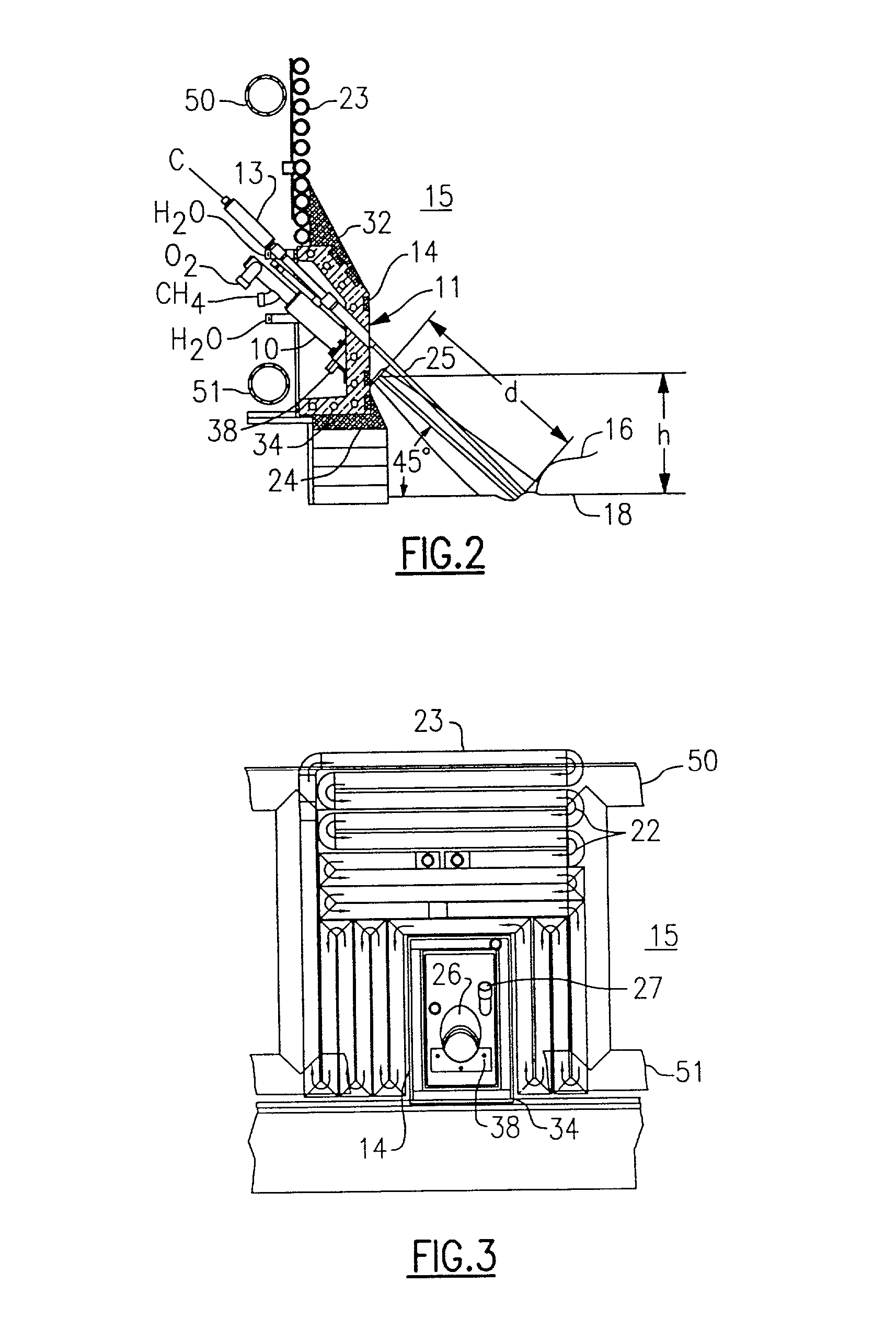
[0061] In an illustrated first embodiment in FIGS. 1-4, the injection apparatus 11 preferably includes a burner / lance 10, a particulate injector 13 and a mounting enclosure 14. Preferably, the burner / lances 10 can be those described previously in the Shver, Shver, et al. I or II references, but they could also be other commercially available air fuel burners; oxygen fuel burners; oxygen, air and fuel burners; and / or oxygen injectors. Preferably, the particulate injector 13 comprises a hollow pipe through which particulates entrained in a carrier gas, such as carbon particles carried by pressurized air, can be introduced into the furnace 15. Preferably, the mounting enclosure 14 can be any those disclosed in the incorporated references, U.S. Ser. Nos. 09 / 502,064; 09 / 875,153; or 09 / 902,139. Specifically, additional details as to the construction and operation of the injection apparatus 11 of FIGS. 1-4 are disclosed in Ser. No. 09 / 902,139.
[0062] While the preferred embodiments of the i...
second embodiment
[0098] While the second embodiment illustrates a particular positioning for the particulate injectors 9 and 13, it is evident that many other different positionings can be envisioned within the scope of the invention. One or more particulate injectors may be mounted in the enclosure 14 at various places to produce a flow of particulate materials establishing one or more particulate reaction zones on the periphery of the oxidation reaction zone. Those particulate reaction zones established on the downstream side of the oxidation reaction zone 52 (to the right of centerline 73) reduce a part of the FeO from the oxidation reaction zone and cool the slag. Those particulate reaction zones established between the oxidation reaction zone 52 and the refractory 21 (below centerline 75) reduce a part of the FeO from the oxidation reaction zone 52 and cool the slag before it reaches the refractory. When multiple oxidation reaction zones are used in a system, each oxidation reaction zone may ha...
PUM
| Property | Measurement | Unit |
|---|---|---|
| particulate injection angle | aaaaa | aaaaa |
| injection angle | aaaaa | aaaaa |
| angle | aaaaa | aaaaa |
Abstract
Description
Claims
Application Information
 - R&D
- Intellectual Property
- Life Sciences
- Materials
- Tech Scout
- Unparalleled Data Quality
- Higher Quality Content
- 60% Fewer Hallucinations
Browse by: Latest US Patents, China's latest patents, Technical Efficacy Thesaurus, Application Domain, Technology Topic, Popular Technical Reports.
© 2025 PatSnap. All rights reserved.Legal|Privacy policy|Modern Slavery Act Transparency Statement|Sitemap|About US| Contact US: help@patsnap.com


