
Heat shield resistant to extreme high temperature and strong impact and manufacturing method thereof

A high-heat, high-endurance technology, applied in the field of thermal management, can solve the problems of short endurance time, low temperature of phase change point, latent heat of phase change and not too high heat capacity, etc., to achieve a slow increase in temperature, increase heat transfer thermal resistance, The effect of large latent heat of phase change

Pending Publication Date: 2022-05-27
何郧
View PDF0 Cites 0 Cited by
  • Summary
  • Abstract
  • Description
  • Claims
  • Application Information

AI Technical Summary

Problems solved by technology

However, the disadvantages of this method are also obvious. First, the phase change point temperature of alcohol wax or fat wax-based phase change material is relatively low, and it is easy to flow, which will cause the phase change of the heating device in the daily working environment. And change the initial package state, resulting in difficulties in the daily maintenance and repair of heating devices; secondly, the phase change latent heat and heat capacity of alcohol wax or fat wax based phase change materials are not too high, and the endurance time under extreme high temperature conditions is relatively short , once the phase transition of all the materials occurs, the temperature of the materials rises very quickly

Method used


Image

  • Heat shield resistant to extreme high temperature and strong impact and manufacturing method thereof

Examples


Embodiment 1

[0042] 20 g of stearic acid and 1.3 g of sodium dodecyl methyl sulfate were mixed, added to 160 ml of deionized water, and magnetically stirred at 80° C. for 1 hour to make the mixture uniform to form A solution. Then add 12ml of MTMS (methyltrimethoxysilane) and 12ml of TEOS ethyl orthosilicate to mix with an appropriate amount of anhydrous ethanol, and then add dilute hydrochloric acid to condition the pH to make the solution pH between 2 and 3, and at 80 ° C Magnetic stirring was carried out at 400 rpm for 30 min to form B solution. The A solution was added dropwise to the B solution and stirred magnetically at 400 rpm for 2 hours at 80°C. Then, ultrasonically vibrate the mixed solution for 30 min, filter and dry to obtain a white phase-change setting material; mix the obtained phase-change setting material, expanded perlite, and halloysite nanotubes in a ratio of 7:2:1 to obtain Inorganic particles containing shape-setting phase change material; gum arabic, hydroxymethyl ...

Embodiment 2

[0044]TEOS (ethyl orthosilicate) was mixed with purified water in a molar ratio of 2:3, and magnetically stirred at 400 rpm for 30 min at 30 °C. After that, add dilute hydrochloric acid to condition the pH to make the solution pH between 2 and 3. Then an appropriate amount of CTAB (hexadecyltrimethylammonium bromide), deionized water and absolute ethanol were added in sequence. And stirred at 13000rpm for 10min. After that, an appropriate amount of 25wt% ammonia water was added, and after 10 hours of reaction, it was taken out for filtration, and after freeze-drying, a white phase change material was obtained; the obtained phase change material and silica aerogel were subjected to a 2:1 ratio The proportions are mixed evenly to obtain inorganic particles containing the shape-setting phase change material; gum arabic, hydroxymethyl cellulose and water-soluble phenolic resin are mixed uniformly in a ratio of 1:1:2 to form a mixed resin adhesive; then 59 % mass fraction of inor...


PUM


Abstract

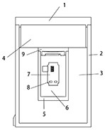
The invention discloses a heat insulation protection device for protecting special electronic products from extreme high-temperature environments (such as ground fire, explosion or airplane crash) and strong impact. The heat insulation protection device generally mainly comprises an outer shell, an outer cavity heat insulation layer, an inner shell and an inner cavity heat insulation layer. Some small equipment or structural bodies only comprise two parts, namely an outer shell and an outer cavity heat insulation layer. The outer shell is made of titanium alloy or special steel which is high in specific strength, high in compression resistance and penetration resistance and high in melting point. The outer cavity heat insulation layer is a powder material integrally formed through high-pressure mold pressing, the material has a shape-stabilized phase change material with low thermal conductivity and a high-temperature phase change characteristic, and the main components of the material comprise an inorganic particle material, a phase change shape-stabilized material, an endothermic oxide, inorganic fibers and a mixed resin adhesive. The inner cavity shell is made of titanium alloy, stainless steel or refractory fiber materials with high modulus and high heat capacity. The material of the inner cavity heat insulation layer does not need compression molding, and the components can be the same as those of the outer cavity heat insulation layer or other phase change materials.

Description

technical field [0001] The invention belongs to the field of thermal management, and in particular relates to a heat shield capable of withstanding high heat flux fire and strong impact, and capable of maintaining safe storage and operation of internal storage devices or electrical products, and a manufacturing method thereof. Background technique [0002] Electronic products are heat-sensitive devices, and an increase in ambient temperature directly leads to an increase in device temperature. All electronic components have a certain temperature range for normal operation or storage. Once the temperature limit is exceeded, it will directly lead to its state change, damage, and even self-burning. Therefore, the thermal protection of electronic products is particularly important. [0003] The thermal protection for some high-power or heat-sensitive electronic products is extremely difficult even in the daily working environment, which has long plagued relevant experts and sch...

Claims


Application Information

Patent Timeline
IPC IPC(8): H05K7/20H05K5/02C04B26/28B29C43/02
CPCH05K7/2029H05K5/0217C04B26/285B29C43/02C04B2111/763C04B24/38C04B24/307C04B24/42C04B14/42C04B14/303C04B14/185C04B24/40C04B24/04C04B24/16C04B24/026C04B14/04C04B22/082Y02E60/14
Inventor 何郧
Owner 何郧
Learn More