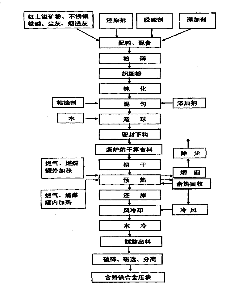
Process and device for preparing iron alloy containing nickel and nickel-chromium
A preparation process, ferroalloy technology, applied in the field of non-ferrous metallurgy, can solve the problems of high sulfur content, complex process, unfavorable dephosphorization outside the furnace, etc.
- Summary
- Abstract
- Description
- Claims
- Application Information
AI Technical Summary
Problems solved by technology
Method used
Image


Examples
Embodiment 1
[0060] Embodiment 1: the equipment scheme that the present invention solves its technical problem is:
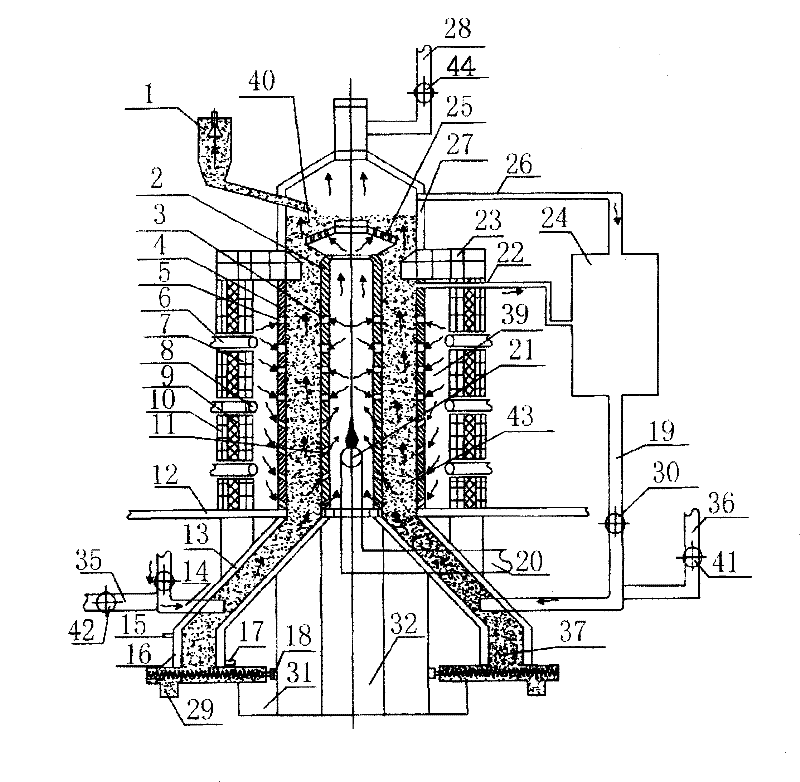
[0061] The reduction equipment includes a furnace base 12, an upper furnace body, a lower furnace body, an upper furnace cover, a drying bed furnace grate 25, a sealed blanking device 1, a purification device and a waste heat circulation device. The upper furnace body is connected with the lower furnace body under the furnace base, and the furnace cover is connected with the upper end of the upper furnace body. The drying bed furnace grate is located at the upper end of the upper furnace body. Connection, the waste heat circulation device is connected with the lower furnace body.
[0062]The upper furnace body includes an inner heating tank 2, a reducing gas outlet 3, an outer heating reduction tank 4, a heating air inlet 5, a gas pipe 6, a refractory brick 7, a gas nozzle 8, a refractory fiber 9, a reduction furnace shell 10, Intake hole 11 of inner and outer heating tank,...
Embodiment 2
[0093] Embodiment 2: the equipment scheme that the present invention solves its technical problem is:
[0094] exist image 3 Among them, the upper furnace body includes an inner heating tank 2, a reducing gas outlet 3, an outer heating reduction tank 4, a heating air inlet 5, a refractory brick 7, a refractory fiber 9, a reduction furnace shell 10, and an inner and outer heating tank air inlet 11. Coal-fired combustion chamber 33, slag discharge chamber 34, internal heating flue 38, heating chamber 39, roasting reduction area 43, reduction furnace shell, refractory brick layer, external heating reduction tank and internal heating tank are set in sequence, and the reduction furnace shell Located at the outermost layer, the inner heating tank is located at the innermost layer, the coal-fired combustion chamber 33 and the slagging chamber 34 are located at the lower end of the upper furnace body, and the inner heating fire channel 38 is located at the lower end of the inner heat...
Embodiment 3
[0106] Embodiment 3: the equipment scheme that the present invention solves its technical problem is:
[0107] exist Figure 4 Among them, the upper furnace body is a porous one-channel furnace body structure, and the layout of the furnace body is a single row and one channel. In the figure, 1-1 is a heater, 1-2 is an outer furnace body, and 1-3 is an internal and external heating Reduction tanks, 1-4 are heating chambers, and each furnace body uses the same heating channel; there are 4 external heating reduction tanks and internal heating tanks distributed in the upper furnace body, and the middle and lower parts of the external heating reduction tanks and internal heating tanks There are 18 air inlets and outlets that are oblique to the vertical line of the tank body, and there are air inlets and outlets arranged parallel to the tank body in the middle and upper part of the tank body, and the air inlets and outlets are evenly distributed on the tank body; the shape of the ex...
PUM
 Abstract
Description
Claims
Application Information
 - R&D
- Intellectual Property
- Life Sciences
- Materials
- Tech Scout
- Unparalleled Data Quality
- Higher Quality Content
- 60% Fewer Hallucinations
Browse by: Latest US Patents, China's latest patents, Technical Efficacy Thesaurus, Application Domain, Technology Topic, Popular Technical Reports.
© 2025 PatSnap. All rights reserved.Legal|Privacy policy|Modern Slavery Act Transparency Statement|Sitemap|About US| Contact US: help@patsnap.com