Processor with low overhead predictive supply voltage gating for leakage power reduction

a technology of leakage power reduction and predictive supply voltage, which is applied in the direction of program control, liquid/fluent solid measurement, instruments, etc., can solve the problems of subthreshold leakage of substantial portion of chips, increased active chip power consumption, linear increase in chip leakage or standby power, etc., and achieves the effect of reducing processor power consumption and without appreciable performance loss

Active Publication Date: 2006-11-07
IBM CORP
View PDF11 Cites 28 Cited by
  • Summary
  • Abstract
  • Description
  • Claims
  • Application Information

AI Technical Summary

Benefits of technology

[0026]It is a purpose of the present invention to reduce p...

Problems solved by technology

Thus, not withstanding the decrease of chip supply voltage, active chip power consumption has increased as well.
Moreover, independent of operating frequency, chip leakage or standby power increases linearly with the number of chip transistors.
Especially for chips and circuits in the insulated gate field effect transistor (FET) technology commonly referred to as CMOS, a substantial portion of chip leakage is subthreshold leakage.
Thus, even if chip active power is reduced to zero, i.e., effectively the chip is shut down, subthreshold leakage continues to consume power.
Consequently, both at the chip and system levels cooling and packaging costs have escalated as a natural result of these chip power increases.
Thus, particularly with state of the art central processing units (CPUs), even with the advances in CPU architecture, whether a scalar, superscalar, vector, or some other type of processor, this increase in microprocessor power dissipation has become a major stumbling block for performance gains.
However, bus and off-chip memory speeds have not kept pace with processor computing logic core.
There are at least two problems arising from coarse idle control that must be addressed.
First, large transient current drops and gains can cause unacceptable levels of inductive (LdI/dt) noise in on-chip supply voltage.
Second, overhead cycles are required for gating off and on processes to maintain correct functional operation.
Switching between gated and enabled modes too frequently for finer grain phase changes in the workload results in an unacceptable performance hit.
These state of the art approaches do not...

Method used


Image

  • Processor with low overhead predictive supply voltage gating for leakage power reduction
  • Processor with low overhead predictive supply voltage gating for leakage power reduction
  • Processor with low overhead predictive supply voltage gating for leakage power reduction

Examples


Embodiment Construction

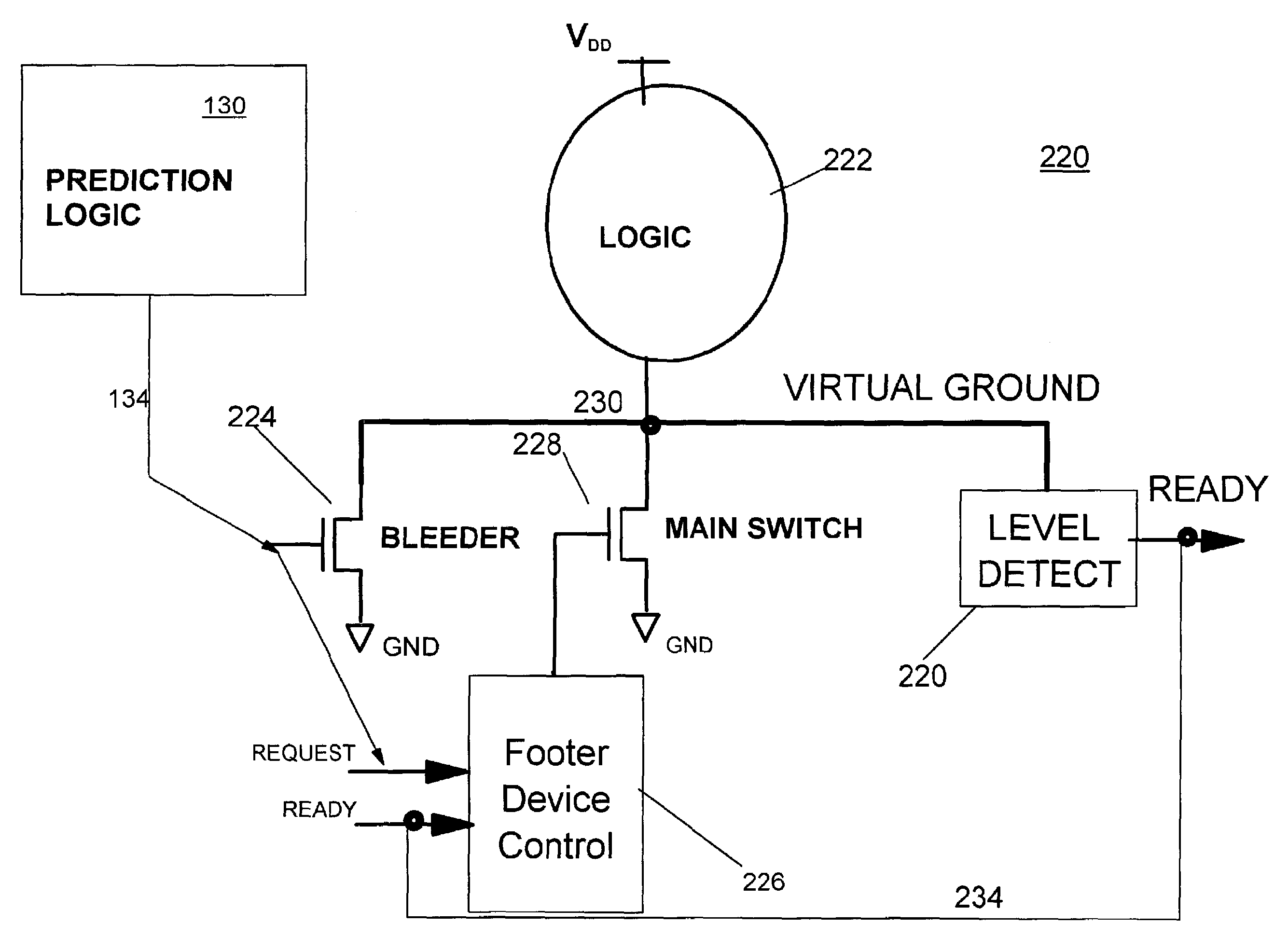
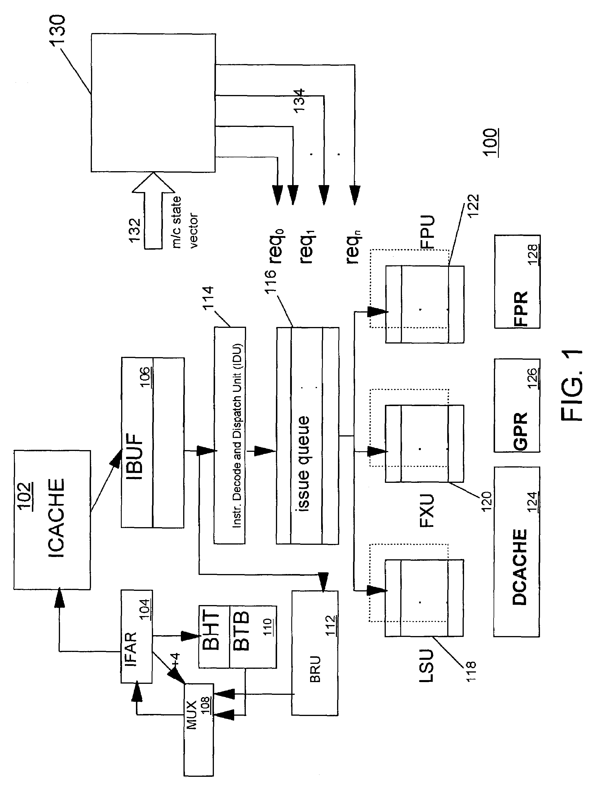
[0036]Turning now to the drawings and, more particularly, FIG. 1 shows a high level block diagram example of a preferred embodiment component (a processor 100 in this example) with subthreshold leakage power consumption reduction and control according to the present invention. In particular, component circuits or units share a common supply or multiple supply voltage (Vdd) sources. Average component leakage power is reduced without appreciable performance degradation, e.g., as measured using instructions per cycle (IPC) and without requiring significant additional hardware. Further, reliable component operation is maintained with a tight control on inductive noise (LdI / dt) effects. Where maximum power dissipation (and hence temperature) limits are rigidly constrained, power consumption is controlled with a minimal performance loss over a small, predetermined time window to maintain the component at or return the component to normal operating conditions.

[0037]The present invention ha...


PUM


Abstract

An integrated circuit (IC) including unit power control, leakage reduction circuit for controllably reducing leakage power with reduced LdI/dt noise in the IC and, an activity prediction unit invoking active/dormant states in IC units. The prediction unit determines turn on and turn off times for each IC unit. The prediction unit controls a supply voltage select circuit selectively passing a supply voltage to a separate supply line at the predicted turn on time and selectively blocking the supply voltage at the predicted turn off time.

Description

BACKGROUND OF THE INVENTION[0001]1. Field of the Invention[0002]The present invention generally relates to the reduction and control of power consumption in a microprocessor or system comprised of a plurality of clocked components or units.[0003]2. Description of the Related Art[0004]Semiconductor technology and chip manufacturing advances have resulted in a steady increase of on-chip clock frequencies, the number of transistors on a single chip, the chip die size itself and, a corresponding decrease in chip supply voltage (Vdd). Generally, the active power consumed by a given clocked unit is primarily from switching chip capacitive loads and increases linearly with the clock frequency. Thus, not withstanding the decrease of chip supply voltage, active chip power consumption has increased as well.[0005]Moreover, independent of operating frequency, chip leakage or standby power increases linearly with the number of chip transistors. Especially for chips and circuits in the insulated ...

Claims


Application Information

Patent Timeline
IPC IPC(8): G06F1/26G06F1/32G06F9/38G06F15/78
CPCG06F1/3203G06F1/3243G06F1/3246G06F9/3869G06F1/3287Y02B60/1282Y02B60/1239Y02D10/00
Inventor BOSE, PRADIPBROOKS, DAVID M.COOK, PETER W.EMMA, PHILIP G.GSCHWIND, MICHAEL K.SCHUSTER, STANLEY E.SRINIVASAN, VIJAYALAKSHMI
Owner IBM CORP
Why Eureka
Try Eureka