
Liquid crystal polymer film, laminate, method of making them and multi-layered parts-mounted circuit board

a liquid crystal polymer film and circuit board technology, applied in the direction of transportation and packaging, other domestic articles, synthetic resin layered products, etc., can solve the problems of liquid crystal polymer itself being thermally decomposed, prone to bulging, peeling and/or thermal deformation of the base film in the fpc board, and the relatively high molding temperature required accompanied by consumption of a relatively large amount of energies

Inactive Publication Date: 2001-08-14
KURARAY CO LTD
View PDF20 Cites 114 Cited by
  • Summary
  • Abstract
  • Description
  • Claims
  • Application Information

AI Technical Summary

Benefits of technology

The film prepared from any of those liquid crystal polymers discussed above can be made by the use of one or a combination of the well-known T-die process and the well-known inflation process. Particularly with the inflation method, stresses can be applied not only in a direction of the mechanical axis of the film (which direction is hereinafter referred to as the MD direction), but also in a direction (hereinafter referred to as TD direction) perpendicular to the MD direction and, therefore, the inflation method is effective, and is therefore advantageously employed, to eventually manufacture the liquid crystal polymer film having balanced physical and thermal properties in both of the MD and TD directions.
As a material for the base material to be laminated with the liquid crystal polymer film of the kind discussed above, the material having a melting point higher than that of such liquid crystal polymer film, such as a metal including, for example, copper, nickel, aluminum, silver or gold, or an inorganic material such as glass, and capable of supporting the shape of such liquid crystal polymer film during the heat treatment can be suitably employed. Since as the base material, particularly the metal, has a high thermal conductivity, it can be effectively employed to facilitate increase of the temperature of the liquid crystal polymer film to a desired temperature during the heat treatment and, hence, to reduce the time required to complete the heat treatment. The base material employed in the practice of the present invention may be in any suitable form, for example, in the form of a film, a sheet or a plate, provided that it has a surface with or without fine surface irregularities, which is generally flat so as to support the liquid crystal polymer film so that during the heat treatment any undesirable flow of the liquid crystal polymer film can be prevented. The base material may advantageously be employed in the form of a metal foil or, in particular, a copper foil. The base material may have any suitable thickness which may be selected depending on a particular application and preferably has a thickness within the range of 10 to 1,000 .mu.m where the laminate of the present invention is, for example, used in FPC boards. On the other hand, where the film deposited base material is used as an insulating material in a heat radiating plate for efficiently dissipating heat evolved by a loss of electric power during operation of a semiconductor device, the heat radiating plate preferably has a thickness within the range of 0.1 to 5 mm. Also, where the liquid crystal polymer film is desired to be produced by peel-off from the base material, the thickness of the base material within the range of 0.03 to 0.1 mm is preferred.

Problems solved by technology

However, since the polyethylene terephthalate film has an insufficient heat resistance, it has been found problematic in that when electric and / or electronic component parts are mounted on the FPC board and when the FPC board with the electric and / or electronic component parts thereon is subsequently dipped in a solder bath, the base film in the FPC board is susceptible to bulging, peel-off and / or thermal deformation.
However, since the liquid crystal polymer generally has a high heat resistance, and when the liquid crystal polymer is desired to be molded into a film, not only is a relatively high molding temperature required accompanied by consumption of a relatively large amount of energies, but also the liquid crystal polymer itself tends to be thermally decomposed.
Although of the various liquid crystal polymers the liquid crystal polymer capable of being molded at a relatively low molding temperature is available, it has often been found that the resultant film made of that liquid crystal polymer tends to have a low heat resistance and can, therefore, not be suited as a material for the heat resistant base film.
Also, no means is employed to allow the liquid crystal polymer film to retain its shape and the film tends to loose its shape when heated to a temperature approaching the melting point of the liquid crystal polymer and, therefore, the film having an excellent appearance is hardly obtainable.
More specifically, if the film itself is heat-treated at a temperature not lower than the thermal deformation temperature at which thermal deformation is initiated, the film is susceptible to deformation and stress build-up and thermal deformation is pronounced particularly where the film has a small thickness.
This heat-treatment requires an increased length of time until the film gains a required heat resistance, accompanied by reduction in productivity.
However, the method has not yet been made available that is effective to accomplish the intended heat treatment optimally without allowing the film to be thermally deformed and to retain its shape throughout the heat-treatment process.
In addition, in order for the film to be available as a commercial and / or industrial product, the film must be of a kind capable of being manufactured consistently and continuously, however, the method accomplishing this has not yet been known in the art.
Accordingly, this known method is incapable of providing the liquid crystal polymer film having a high heat resistance and a high strength.
If the heat-treating condition departs from the specific heat-treating condition specified hereinbefore, the base material will undergo discoloration and will be unable to exhibit a desired heat resistance and a desired flexibility.
Considerable departure from the specific heat-treating condition would result in, for example, an undesirable deformation of the liquid crystal polymer film separated or delaminated from the laminate.
On the other hand, if the parameter a is larger than 35.degree. C., the heat-treating temperature would be undesirably so low as to increase the heat-treating time and is therefore unpractical.
However, where the heat-treating temperature employed during the second heat treatment is higher than the fusion peak temperature TA.sub.1 that has increased as a result of the first heat treatment, the heat resistance of the liquid crystal polymer will return to the melting point Tm of such polymer before the heat treatment with the effect of the first heat treatment consequently lost.
If the temperature increment .beta. of the fusion peak temperature TA brought about by the first heat treatment is lower than 5.degree. C., the temperature control of a heat-treating furnace will be difficult to achieve.
The higher the bonding strength before the heat treatment, the higher the morphological stability of the polymer film, and where it is low, an adverse influence will be brought about such as delamination and / or thermal tear.
On the other hand, the lower the bonding strength after the heat treatment, the higher the delamination stability, and where the bonding strength is high, the possibility will arise that the polymer film may break during the delimitation in the presence of even a slight scratch.
On the other hand, if the maximum surface roughness is greater than 10 .mu.m, the polymer film, particularly the thin film, may be prone to tear in a direction across the thickness thereof and may therefore be easily break during the delamination of the polymer film from the base material.
If the thickness of the silicone polymer is smaller than 0.1 .mu.m, delamination of the polymer film from the base material will be difficult to achieve, but if it is greater than 1 .mu.m, the possibility will arise that although delamination between the polymer film and the base material can be easily achieved, not only may a substantial amount of the silicone polymer be wasted, but also the silicone polymer will stick to the liquid crystal polymer film to such an extent as to result in delamination from the base material, resulting in incapability of the base material being reused.

Method used


Image

  • Liquid crystal polymer film, laminate, method of making them and multi-layered parts-mounted circuit board
  • Liquid crystal polymer film, laminate, method of making them and multi-layered parts-mounted circuit board
  • Liquid crystal polymer film, laminate, method of making them and multi-layered parts-mounted circuit board

Examples


example 1

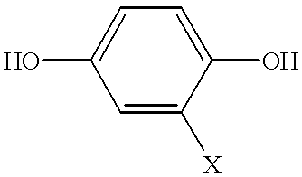
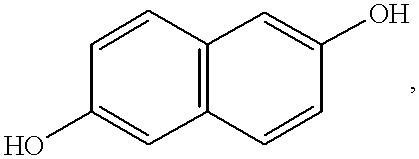
(1) In the first place, a thermotropic liquid crystal polyester containing 27 mol % of units from 6-hydroxy-2-naphthoic acid and 73 mol % of units from p-hydroxybenzoic acid was heat-kneaded through a single-screw extruder at a temperature of 280 to 300.degree. C. and was then extruded through an inflation die, 40 mm in diameter and 0.6 mm in slit size, to produce a liquid crystal polymer film having a thickness of 50 .mu.m The resultant liquid crystal polymer film had a melting point Tm of 280.degree. C. and a thermal deformation temperature Tdef of 230.degree. C.

(2) Also, using a copper foil (1 / 2 ounce copper foil based on the electrolytic method) of 18 .mu.m in thickness as the base material, this copper foil was thermally pressed to the above described film at 260.degree. C. to produce a laminate.

(3) In order to measure change of the melting point resulting from the heat treatment of this laminate, the fusion peak temperature TA of the film layer was measured at intervals of one...

example 2

The laminate and the film were obtained in a manner similar to Example 1, except that the laminate obtained as in (2) in Example 1 was fixed horizontally in the nitrogen atmosphere within a hot air dryer producing a hot gas of 260.degree. C. in such a positional relationship that the film surface was oriented upwards while the copper foil surface was oriented downwards, to cause the film surface temperature to be increased to 260.degree. C., and the heated laminate was heat-treated at this temperature for four hours and was, after the temperature had subsequently been increased to 300.degree. C., further heat-treated for six hours. Similar tests to those in Example 1 were conducted on the resultant laminate and the film, results of which are tabulated in Table 6.

example 3

The laminate and the film were obtained in a manner similar to Example 1, except that the laminate obtained as in (2) in Example 1 was fixed horizontally in the nitrogen atmosphere within a hot air dryer producing a hot gas of 260.degree. C. to cause the film surface temperature to be increased to 260.degree. C., and the heated laminate was heat-treated at this temperature for two hours and was, after the temperature had subsequently been increased to 290.degree. C., further heat-treated for six hours. Similar tests to those in Example 1 were conducted on the resultant laminate and the film, results of which are tabulated in Table 6.


PUM

PropertyMeasurementUnit
melting point Tmaaaaaaaaaa
fusion peak temperature TA1aaaaaaaaaa

Abstract

A polymer film capable of forming an optically anisotropic melt phase is, after having been laminated on a base material capable of supporting the shape of the film during heat treatment, is heat-treated at a temperature of from the thermal deformation temperature Tdef of the film to a temperature lower by alpha (alpha=10 to 35° C.) than the melting point Tm of the film until the fusion peak temperature TA of the film attains a temperature which is higher by beta (beta=5 to 30° C.) than the melting point Tm of the film before the heat treatment and is subsequently heat-treated at a temperature of from a temperature not lower than the melting point Tm of the film to a temperature lower than the fuision peak temperature TA for a length of time over which the TA increases by gamma (gamma=5 to 20° C.), and thereafter the base material is removed to produce the film.

Description

1. (Field of the Invention)The present invention relates to a film comprising a polymer capable of forming an optically anisotropic melt phase, a laminate comprising a base material applied with the polymer film, a method of making them and a multi-layered parts-mounted circuit board utilizing the laminate.In the description that follows, the polymer capable of forming an optically anisotropic melt phase is referred to as the "liquid crystal polymer".2. (Description of the Prior Art)Recently in the field of electric and electronic industry, demands for flexible printed circuit boards (hereinafter referred to as "FPC boards") are increasing to cope with the need to make electric and electronic appliances compact and lightweight. The standard method of making the FPC boards comprises preparing a laminate made up of a base film having at least one of its opposite surfaces applied with a metal foil such as, for example, a copper foil and forming a pattern of electric circuits on the lam...

Claims


Application Information

Patent Timeline
Patent Type & Authority Patents(United States)
IPC IPC(8): B32B27/28C08J5/18H05K1/03H05K1/00C08L67/00C08L77/12H05K3/46
CPCB32B27/28C08J5/18H05K1/0313H05K3/4676C08J2367/00Y10T428/31504Y10T428/31786B29C71/02B32B15/08B32B38/0036B32B2457/08
Inventor ONODERA, MINORUTANAKA, YOSHINOBU
Owner KURARAY CO LTD
Learn More