
High aspect ratio catalytic reactor and catalyst inserts therefor

a catalytic reactor and high aspect ratio technology, applied in the direction of physical/chemical process catalysts, metal/metal-oxide/metal-hydroxide catalysts, bulk chemical production, etc., can solve the problem of catalyst attrition, suboptimal reactor performance, and catalyst particle slumping at reactor heat up, etc. problem, to achieve the effect of high thermal conductivity, low thermal expansion rate, and strong spiral monolith structur

Active Publication Date: 2017-06-29
PRAXAIR TECH INC
View PDF8 Cites 12 Cited by
  • Summary
  • Abstract
  • Description
  • Claims
  • Application Information

AI Technical Summary

Benefits of technology

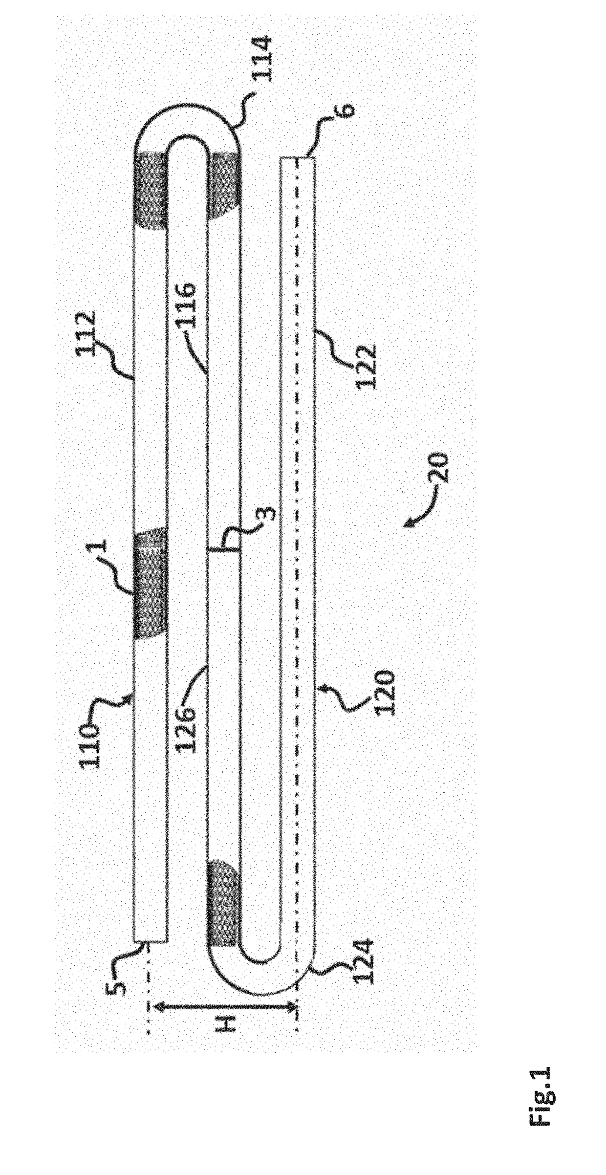
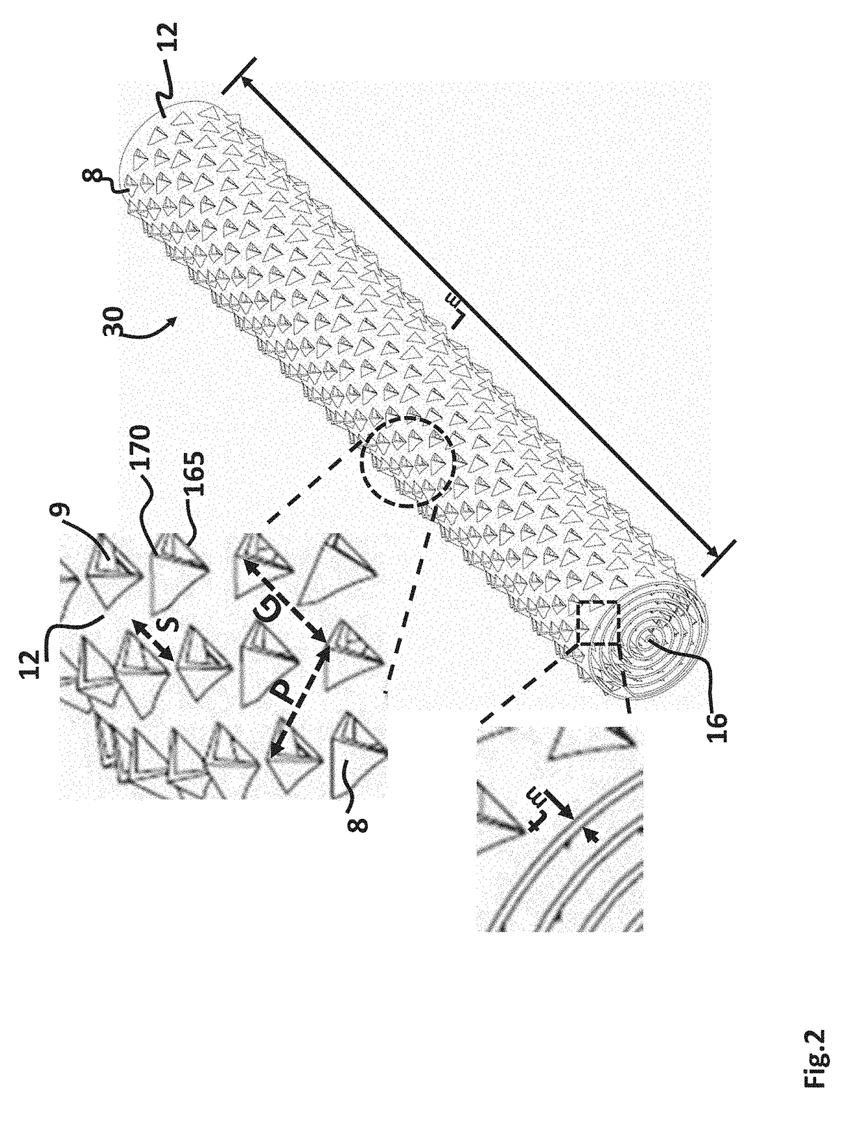
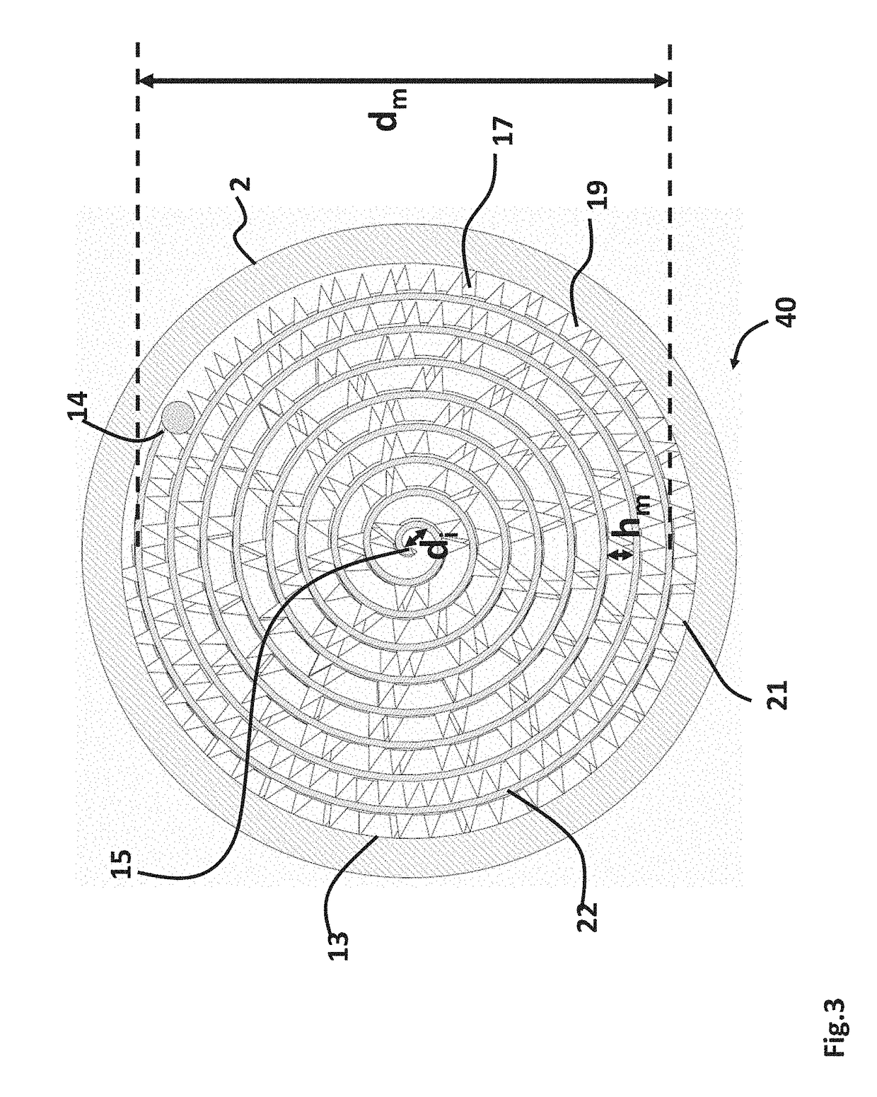
The present invention relates to a new type of tubular reactor for catalytic steam reforming of hydrocarbon fuels. The reactor has a unique arrangement of small diameter, high aspect ratio tubes loaded with catalyst inserts positioned in a non-vertical parallel configuration. The design allows for efficient heat transfer and improved gas mixing while achieving lower pressure drop than known particulate catalysts. The catalyst inserts comprise a three-dimensional metal sheet with surface features such as grooves and peaks that provide mechanical support and open channels for gas flow. The reactor also contains a catalyst that catalyzes reforming reactions and contains at least one Group VIII transition metal. The invention also includes the use of structured catalyst inserts made of high temperature stable metal alloys with high thermal conductivity and low thermal expansion rate. The designed patterns on the foil strengthen the structure and prevent deformation during operation, and also form a plurality of gas channels to enhance gas turbulence and provide high porosity. The technical effects of the invention include improved reaction efficiency, reduced pressure drop, and enhanced gas mixing.

Problems solved by technology

Since the steam reforming process is highly endothermic, external heating sources are required.
Since the catalyst particles have a lower coefficient of thermal expansion, the potential exists for considerable slumping of the catalyst particles upon reactor heat up.
This may cause suboptimal reactor performance due to inadequate heat transfer, higher pressure drop, and increased diffusional resistances.
The potential also exists for catalyst attrition due to crushing forces when the tube contracts.
Non-uniform reforming activity along the length of the tube can cause hot spots raising the tube wall temperature above safe value.
Attempts have been made to address these problems by providing support structures to hold the catalyst particles in position or dividing the catalyst bed within the tube into multiple beds with support structures in between, however these add complexities and can result in undesirable higher pressure drop.
However, structured catalyst inserts for use in conventional SMR reformer tubes have their own design requirements, such as higher heat flux, turbulent gas mixing, lower pressure drop, and high reforming capacity.
However, it is difficult to implement these corrugated metal substrates in small diameter reactors with high aspect ratios because the restrictions of tubing dimension limit the manufacturability of corrugated metal sheet based catalyst inserts and their surface area availability.
It is challenging for direct catalyst coating on tubing wall to achieve high hydrocarbon conversion due to limitation of catalytic surface area and coating delamination at high operating temperature and large temperature gradient across tube wall.
Although the high temperature metal foils such as FeCralloy have been used in catalytic reactors in the past, they have not been usefully employed in high aspect ratio reactors because of the difficulty in establishing a stable supporting structure with adequate open gas channels.

Method used


Image

  • High aspect ratio catalytic reactor and catalyst inserts therefor
  • High aspect ratio catalytic reactor and catalyst inserts therefor
  • High aspect ratio catalytic reactor and catalyst inserts therefor

Examples


example 1

Inserts

[0042]Ferritic chromium steel containing 5.5% aluminum and 0.12% rare earth elements is used as the metallic substrate material. FeCralloy cylinder of 200 mm diameter was first pressed and expanded into a flat metal square foil with thickness of 150 μm. The metal foil was then moved to the stamping machine having rows of tilted blades. Distance of adjacent row of tilted blades was 4 mm and the pitch distance of titled blades in each row was 2.5 mm. The effective blade length was close to 6 mm. The array of blades in zigzag arrangement first slit on one side of the metal foil to form a plurality of cuts and multiples of peaks, then formed on the other side by sandwiching the foil with the blade array and a mold located underneath the foil. The supporting mold was pre-grooved with designed pyramid pattern. The stamped metal foil was cut into a plurality of small square metal foils with dimension of 101 mm (4 inch)×178 mm (7 inch). The tensile strength and yield strength of the ...

example 2

nal Pellet Catalyst

[0047]The reforming catalyst HyProGen® R-70 is a commercially available nickel-based catalyst for steam reforming with high coking resistance. It is cylinder-shape with dimension of 3 mm OD×3 mm length. The reforming catalyst HyProGen® R-70 is randomly packed into the ‘U’ shape piping reformer with path length of 1295 mm (51 inch) and inside diameter of 12.7 mm (0.5 inch). The overall packing density of catalyst in the ‘U’ shape reformer unit is about 1.13 g / mL. Besides two parallel legs of the reformer, the ‘U’ turn path was also filled with pellets and the effective length containing catalyst is 1295 mm. The ‘U’ shape reformer unit packed with R-70 catalyst pellet was loaded vertically in an electrical heating furnace with inlet and outlet ports located on the top of reformer.

[0048]A feed gas mixture, 18 SLPM of methane and 27 SLPM of steam (steam to carbon ratio of 1.5) was preheated prior to entering the inlet of reformer unit. Reactor operating pressure was c...

example 3

Corrugated Monolith

[0049]A flat square expanded Fecralloy foil with dimension of 130 mm (W)×102 mm (L) and thickness of 150 micrometer was obtained from Goodfellow Corporation. The metal foil was mechanically bent to form 18 corrugated channels along foil's width with channel height of 2.5 mm. The dimension of corrugated foil is 33 mm (W)×102 mm (L)×2.5 mm (H). The corrugated foil was rolled tightly to form a spiral monolith and the structure was secured by welding the foil edge to the spiral body. These single-strip corrugated monoliths were spaced and loaded into the electrical-heating furnace for oxidation pretreatment prior to catalyst coating. The monolith samples were exposed to air oxidation at 950° C. for 2 hour with heating ramp rate of 2° C. / min and cooling ramp rate of 2° C. / min.

[0050]The catalyst slurry of Ni—Rh / Al2O3 promoted with CeO2 and YSZ was prepared using the same procedure described in Example 1. After the single-strip corrugated monoliths were pre-oxidized, the...


PUM

PropertyMeasurementUnit
diameteraaaaaaaaaa
porosityaaaaaaaaaa
aspect ratioaaaaaaaaaa

Abstract

The present invention relates to high efficient tubular catalytic steam reforming reactor configured from about 0.2 inch to about 2 inch inside diameter high temperature metal alloy tube or pipe and loaded with a plurality of rolled catalyst inserts comprising metallic monoliths. The catalyst insert substrate is formed from a single metal foil without a central supporting structure in the form of a spiral monolith. The single metal foil is treated to have 3-dimensional surface features that provide mechanical support and establish open gas channels between each of the rolled layers. This unique geometry accelerates gas mixing and heat transfer and provides a high catalytic active surface area. The small diameter, high aspect ratio tubular catalytic steam reforming reactors loaded with rolled catalyst inserts can be arranged in a multi-pass non-vertical parallel configuration thermally coupled with a heat source to carry out steam reforming of hydrocarbon-containing feeds. The rolled catalyst inserts are self-supported on the reactor wall and enable efficient heat transfer from the reactor wall to the reactor interior, and lower pressure drop than known particulate catalysts. The heat source can be oxygen transport membrane reactors.

Description

U.S. GOVERNMENT RIGHTS[0001]The invention disclosed and claimed herein was made with United States Government support under Cooperative Agreement number DE-FC26-07NT43088 awarded by the U.S. Department of Energy. The United States Government has certain rights in this invention.FIELD OF THE INVENTION[0002]The present invention relates to catalytic reactors and catalyst inserts for production of industrial chemicals and intermediates. More particularly, the present invention relates to high efficient tubular catalytic steam reforming reactor with aspect ratio from 50 to 1,000 and tube inside diameter (ID) of from about 0.2 inch to about 2 inches loaded with a plurality of rolled catalyst inserts. The catalyst inserts comprise metallic monoliths having three dimensional surface features that provide mechanical support and establish open gas channels between each of the rolled layers. This unique geometry accelerates gas mixing and heat transfer and provides high catalytic active surfa...

Claims


Application Information

Patent Timeline
Patent Type & Authority Applications(United States)
IPC IPC(8): C01B3/40B01J35/02B01J35/04B01J19/24B01J23/89
CPCC01B3/40B01J19/2415B01J23/894B01J35/04B01J35/023C01B2203/0805C01B2203/0233C01B2203/1023C01B2203/1058C01B2203/1064C01B2203/1241B01J2219/24B01J19/249B01J19/32C01B3/384B01J2219/2454B01J2219/2479B01J2219/30292C01B2203/085C01B2203/1614Y02P20/52B01J19/243B01J15/005B01J19/242B01J19/2485B01J2219/2428B01J2219/2474B01J2219/2482B01J2219/2485B01J2219/2487B01J2219/2495B01J2219/2496B01J2219/30475B01J2219/32251B01J2219/32408B01J2219/32425B01J2219/32466Y02P20/10B01J35/40B01J35/56B01J2219/32248
Inventor LIN, JIEFENGKELLY, SEAN M.
Owner PRAXAIR TECH INC
Learn More