
Niobium powder, niobium granulated powder, niobium sintered body, capacitor and production method thererof

a technology of niobium granules and capacitors, which is applied in the direction of electrolytic capacitors, grain treatment, transportation and packaging, etc., can solve the problems of settling of beads in grinders, disproportionate wear of grinders, and increase the amount of grinding aids mixed into products, and achieves small leakage current values , good reliability

Inactive Publication Date: 2009-10-15
SHOWA DENKO KK
View PDF16 Cites 7 Cited by
  • Summary
  • Abstract
  • Description
  • Claims
  • Application Information

AI Technical Summary

Benefits of technology

The present invention relates to a grinding aid for producing niobium powder. The grinding aid uses a grinding aid that uses a nitride, carbide, or boride as a grinding material. The grinding aid has a density of 2 to 3.6 g / cm2 and a fracture toughness value of 3.5 MPa·m1 / 2 or more. The grinding aid should have a low viscosity of 0.03 Pa·s or less and a thixotropic index of 0.8 or less. By using this grinding aid, the grinding process becomes more efficient, resulting in higher production rates and reduced wear on the grinding equipment. The invention also provides a method for producing niobium powder with a larger capacitance per unit mass and a smaller leakage current with a smaller range of variation compared to conventional methods. The grinding process is carried out at a high concentration of slurry, allowing for efficient production. The grinding aid helps to reduce the viscosity of the slurry and the grinding time period. The grinding aid also helps to reduce the oxygen content in the niobium powder.

Problems solved by technology

Too high a density of the grinding aid tends to cause settling of the beads in the grinder and disproportionate wear of the grinder.
Too low a fracture toughness value of the grinding aid tend to lead to cracking or chipping of the grinding aid, thereby causing an increase in the amount of the grinding aid mixed into a product.

Method used


Image

  • Niobium powder, niobium granulated powder, niobium sintered body, capacitor and production method thererof
  • Niobium powder, niobium granulated powder, niobium sintered body, capacitor and production method thererof
  • Niobium powder, niobium granulated powder, niobium sintered body, capacitor and production method thererof

Examples


example 1

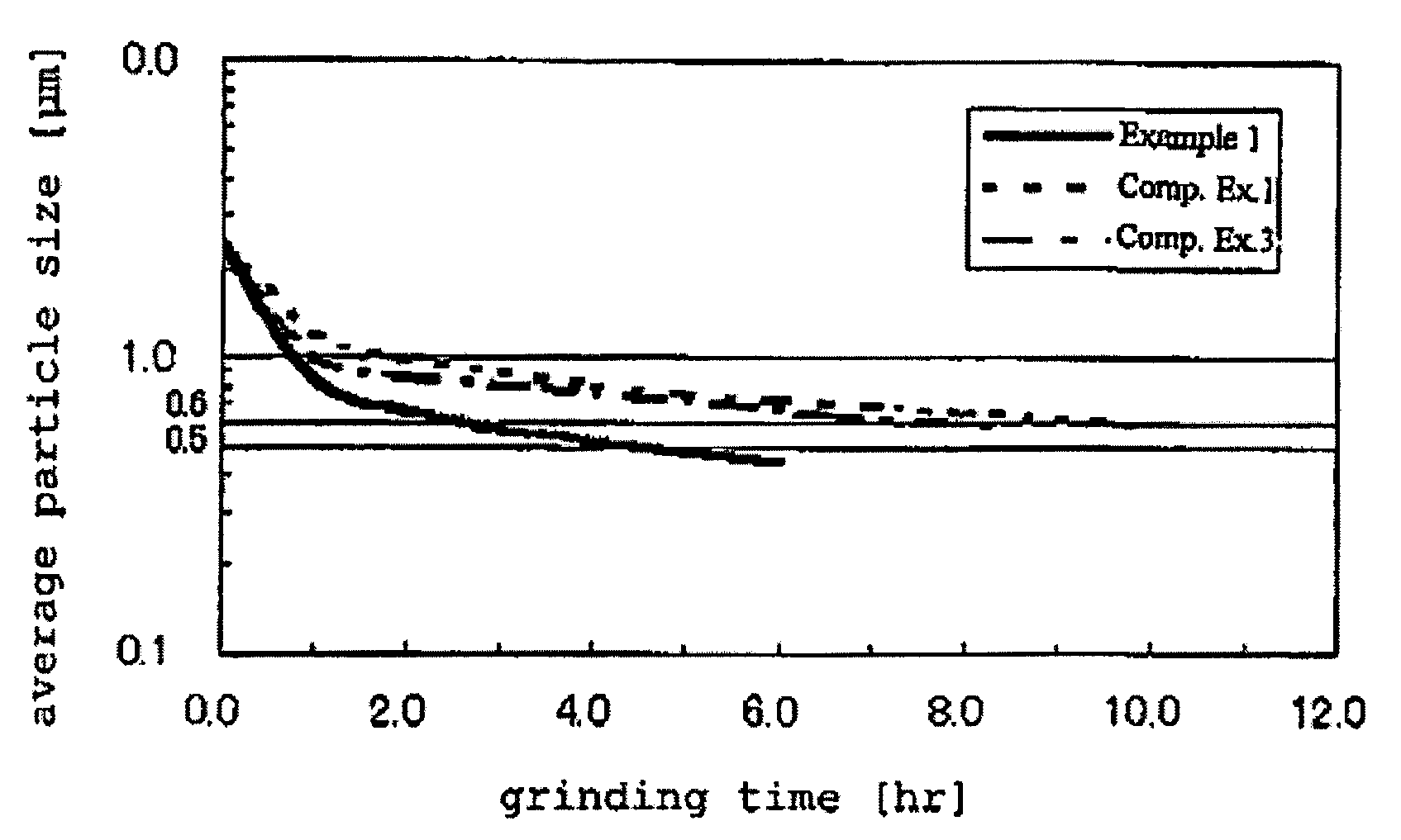
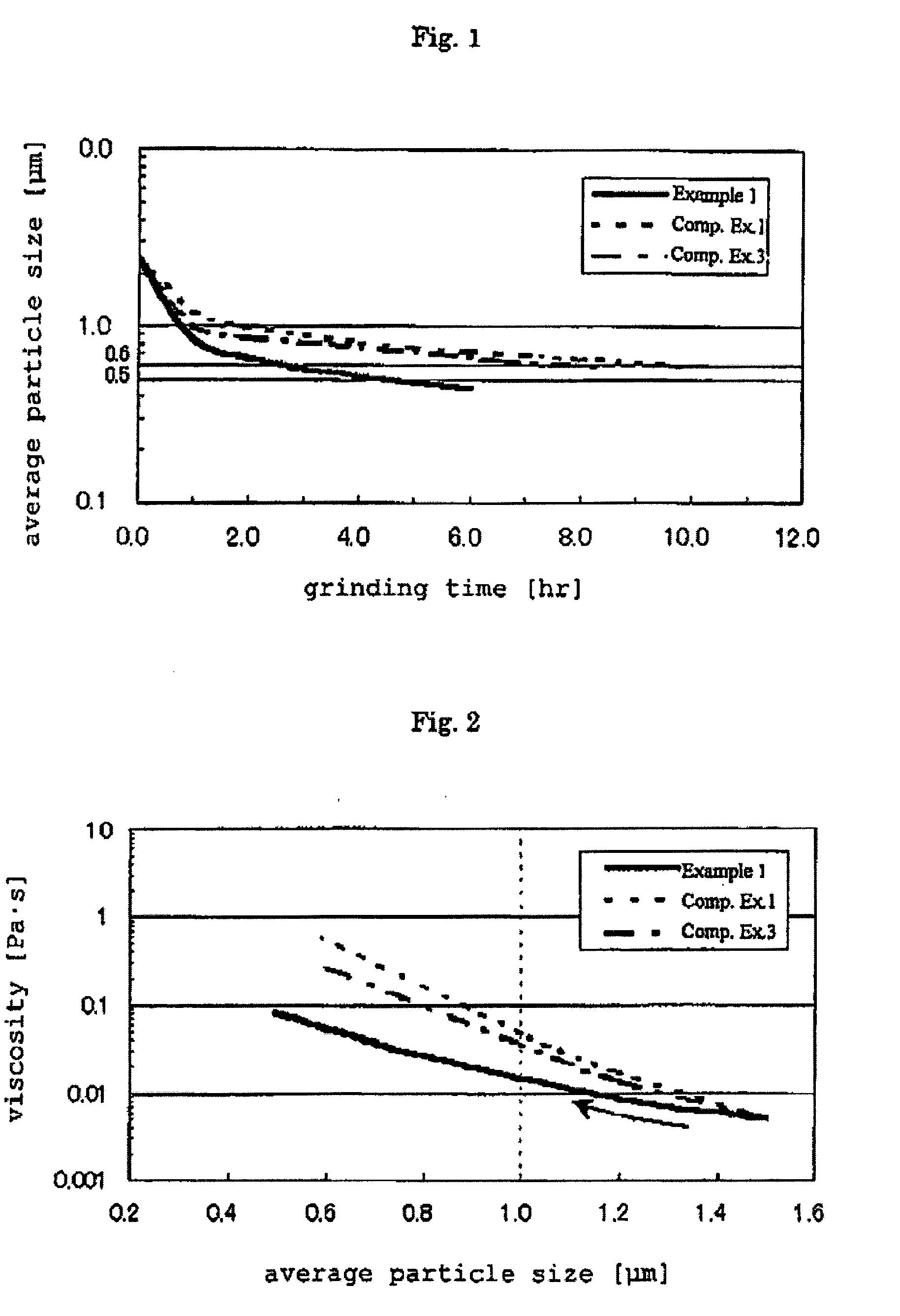
[0083]A niobium ingot (1,000 g) was placed in a reaction vessel made of SUS 304 and hydrogen was then continuously introduced into the reaction vessel at 400° C. for 10 hours. After the reaction vessel had been cooled down to room temperature, under an argon atmosphere, the niobium hydride mass was coarsely crushed with a hammer crusher, thereby obtaining coarse powder of niobium hydride having a particle size of 0.5 mm or less. Subsequently, silicon nitride beads each having a particle size of 0.5 mm (3.2 g / cm3 in density and 6.0 MPa·m1 / 2 in fracture toughness value) provided as a grinding aid and deaerated pure water provided as a dispersion medium were used to carry out a wet-grinding process until the average particle size of niobium hydride coarse powder reached 0.5 μm with a slurry concentration of 40 mass % while cooling from a grinding temperature of 10° C. to 0° C., thereby obtaining water slurry of niobium hydride powder. The viscosity of slurry when the grinding was carri...

examples 2 to 6

[0085]Niobium powder was prepared in the same manner as in Example 1 with variations of dispersion medium, temperature upon grinding, and slurry concentration, followed by preparing granulated powder.

[0086]The niobium granulated powder thus obtained was molded together with a niobium wire having a diameter of 0.3 mm to prepare a compact (about 0.1 g) with dimensions of about 0.3 cm×0.18 cm×0.45 cm. Next, the compact was left standing at 1,250° C. for 30 minutes under a reduced pressure of 4×10⁻³ Pa, thereby obtaining a sintered body. The sintered body thus obtained was subjected to a chemical conversion treatment in a 0.1-mass % aqueous phosphoric acid solution at 80° C. for 6 hours at a voltage of 20 V, thereby forming a dielectric material layer on the surface of the sintered body. After that, the capacitance in 30-mass % sulfuric acid and the leakage current in a 20-mass % aqueous phosphoric acid solution were measured, respectively. The results thereof are represented in Table 1...

example 7

[0087]Niobium hydride coarse powder was subjected to a wet-grinding process until its average particle size reached 0.4 μm in the same manner as in Example 1, thereby obtaining water slurry of niobium hydride powder. Drying was carried out at 40° C. under reduced pressure to obtain niobium hydride powder. The powder had an oxygen concentration of 9.9 mass % and a specific surface area of 13.03 m2 / g. The niobium hydride powder thus obtained wad dehydrogenated at 400° C. for 4 hours at 1×10⁻² Pa, followed by cooling down to room temperature. Under atmospheric pressure, nitrogen was introduced to carry out nitridation at 300° C. for 2 hours. The niobium powder thus obtained was sintered at 1,150° C. for 4 hours under a reduced pressure of 4×10⁻³ Pa, followed by cooling down to room temperature. The resulting niobium mass was crushed to obtain niobium granulated powder. The granulated powder had an average particle size of 105 μm a BET specific surface area of 4.6 m2 / g, a pore size dist...


PUM

PropertyMeasurementUnit
densityaaaaaaaaaa
temperatureaaaaaaaaaa
particle sizeaaaaaaaaaa

Abstract

The present invention provides a method of efficiently producing niobium powder, niobium alloy powder, niobium hydride powder or niobium hydride alloy powder for a capacitor, which enables production of capacitor having a high capacitance per unit mass and good leakage current characteristics with narrow variation, and also provides a production method for sintered body and a capacitor using the niobium powder, niobium alloy powder, niobium hydride powder or niobium hydride alloy powder. According to the present invention, by grinding niobium hydride powder or niobium hydride alloy powder with a grinding aid having a density of 2 to 3.6 g / cm3 and a fracture toughness value of 1.5 MPa·m1 / 2 or more, such as beads made of silicon nitride or a compound containing silicon nitride, a niobium powder with high capacitance can be efficiently produced.

Description

CROSS REFERENCE TO THE RELATED APPLICATIONS[0001]This application is a Divisional of U.S. patent application Ser. No. 11 / 243,992 filed Oct. 6, 2005, which claims benefit of U.S. Provisional application Ser. No. 60 / 618,570 filed Oct. 15, 2004. The above-noted applications are incorporated herein by reference in their entirety.TECHNICAL FIELD[0002]The present invention relates to a production method of niobium powder, niobium alloy powder, niobium hydride powder or niobium hydride alloy powder for a capacitor, which powder consists mainly of niobium and can be used as a raw material for the production of the capacitor. More specifically, the present invention relates to a method of efficiently producing niobium powder, niobium alloy powder, niobium hydride powder or niobium hydride alloy powder for a capacitor with which a capacitor having a high capacitance per unit mass and good leakage current characteristics can be obtained, to a sintered body using such a powder, and to a capacit...

Claims


Application Information

Patent Timeline
Patent Type & Authority Applications(United States)
IPC IPC(8): B02C23/18B02C23/06
CPCB22F9/04B22F2998/10C01B6/02C22C1/045H01G9/042H01G9/0525B22F9/023B22F1/0096
Inventor AMITA, HITOSHIOMORI, KAZUHIRO
Owner SHOWA DENKO KK
Learn More