
Hybrid nano-filament cathode compositions for lithium metal or lithium ion batteries

Inactive Publication Date: 2009-07-23
GLOBAL GRAPHENE GRP INC
View PDF32 Cites 152 Cited by
  • Summary
  • Abstract
  • Description
  • Claims
  • Application Information

AI Technical Summary

Benefits of technology

[0045]An NGP is essentially composed of a sheet of graphene plane or multiple sheets of graphene plane stacked and bonded together through van der Waals forces. Each graphene plane, also referred to as a graphene sheet or basal plane, comprises a two-dimensional hexagonal structure of carbon atoms. Each plate has a length and a width parallel to the graphite plane and a thickness orthogonal to the graphite plane. By definition, the thickness of an NGP is 100 nanometers (nm) or smaller, with a single-sheet NGP being as thin as 0.34 nm. The length and width of a NGP are typically between 0.5 μm and 10 μm, but could be longer or shorter. Several methods can be used to produce NGPs [e.g., Refs. 15-20]. The NGPs, just like other elongate bodies (carbon nano tubes, carbon nano fibers, metal nano wires, etc.), readily overlap one another to form a myriad of electron transport paths for improving the electrical conductivity of the anode. Hence, the electrons generated by the anode active material coating during Li insertion can be readily collected.
[0053]The aforementioned electrochemically active materials, either cathode or anode active materials, when used alone as an electrode active material in a particulate form (particles bonded by a resin binder and mixed with a conductive additives such as carbon black) or thin film form (directly coated on a copper- or aluminum-based current collector), have been commonly found to suffer from the fragmentation (pulverization) problem and poor cycling stability. By contrast, when coated on the exterior surface of multiple conductive filaments to form a hybrid, nano filament web, the resulting electrode exhibits a high reversible capacity, a low irreversible capacity loss, long cycle life, low internal resistance, and fast charge-recharge rates.
[0056](1) During lithium insertion and extraction, the coating layer expands and shrinks. The geometry of the underlying filament (e.g., CNF, CNT, and metal nanowire being elongate in shape with a nano-scaled diameter and NGP being a thin sheet with a nano-scaled thickness) enables the supported coating to freely undergo strain relaxation in transverse directions (e.g., in a radial or thickness direction). The filaments selected in the present invention are chemically and thermo-mechanically compatible with the cathode active material coating, to the extent that the coating does not loss contact with its underlying substrate filament upon repeated charge / discharge cycling. Further, it seems that the aggregate or web of filaments, being mechanically strong and tough, are capable of accommodating or cushioning the strains or stresses imposed on the filaments without fracturing.
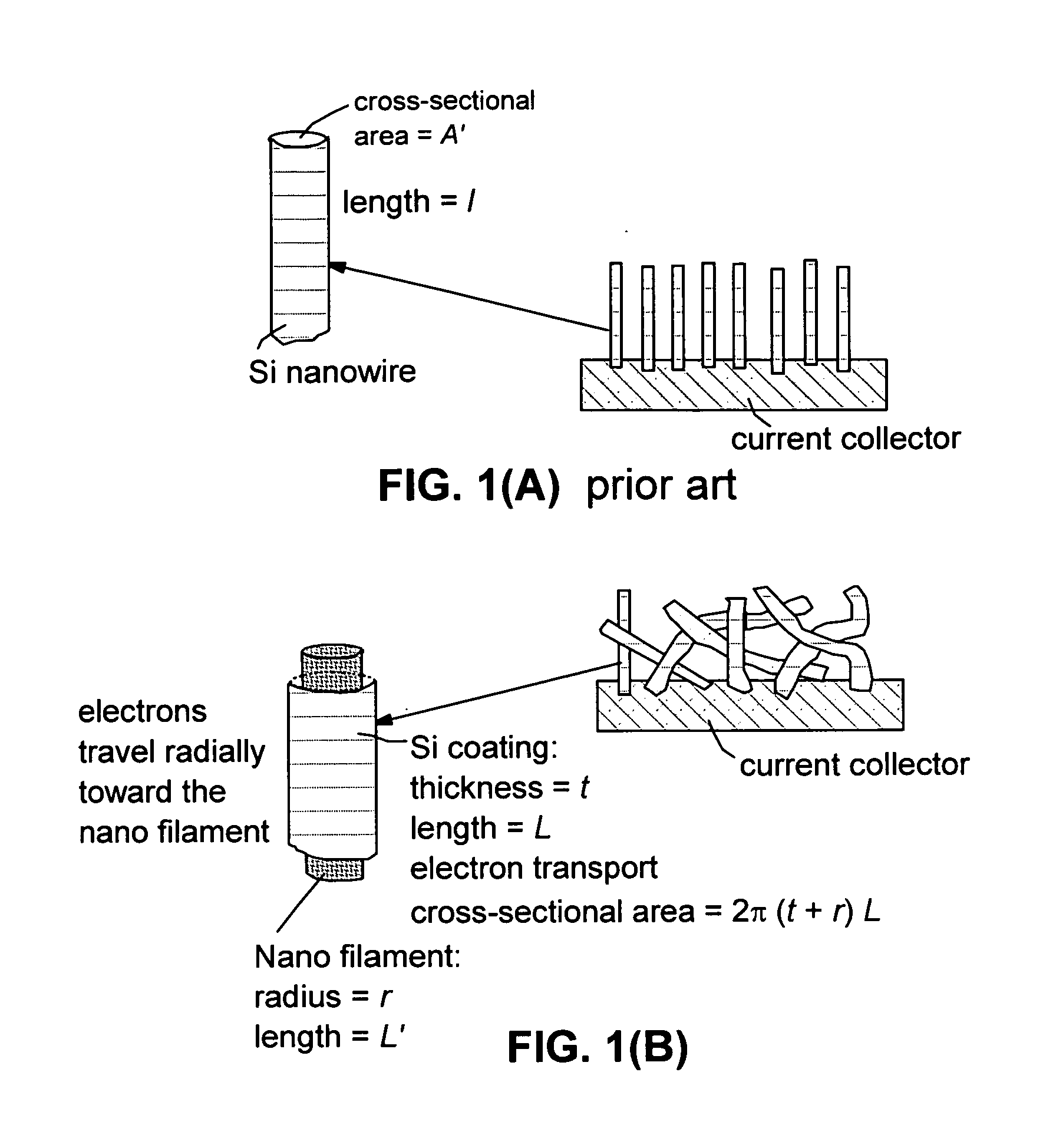
[0059](4) The interconnected network of filaments (schematically shown in FIG. 1(B)) forms a continuous path for electrons, resulting in significantly reduced internal energy loss or internal heating. The electrons that are produced at the anode or those that reach the cathode active material coated on the exterior surface of a filament (with a radius r) only have to travel along a radial direction to a short distance t (which is the thickness of the coating, typically <1 μm) through a large cross-sectional area A, which is equivalent to the total exterior surface of a filament (A=2π[r+t]L). Here, L is the length of the coating in the filament longitudinal axis direction. This implies a low resistance according to the well-known relation between the resistance R1 of a physical object and the intrinsic resistivity ρ of the material making up the object: R1=ρ(t / A)=ρt / (2π[r+t]L)=(3 Ωcm×100 nm) / (6.28×150 nm×10×10−4 cm)=3.2×10²Ω. In this calculation we have assumed r=50 nm, t=100 nm, and L=10 μm. Once the electrons move from the outer coating into the underlying filament, which is highly conductive, they will rapidly travel down the filament longitudinal axis (of length L′) and be collected by a current collector, which is made to be in good electronic contact with the web or individual filaments (ρf=10−4 Ωcm, a typical value for NGPs and graphitized CNFs). The resistance along this highly conductive filament (average travel distance=½L′) is very low, R2=½ρ′(L′ / A″)=½ 10−4 cm×10×10−4 cm / [0.785×10⁻¹⁰ cm2]=6.37×10²Ω. The total resistance=R1+R2=9.57×10²Ω.

Problems solved by technology

These adverse effects result in a significantly shortened charge-discharge cycle life.
However, most of prior art composite electrodes have deficiencies in some ways, e.g., in most cases, less than satisfactory reversible capacity, poor cycling stability, high irreversible capacity, ineffectiveness in reducing the internal stress or strain during the lithium ion insertion and extraction cycles, and some undesirable side effects.
It may be further noted that the cathode materials used in the prior art Li ion batteries are not without issues.
These prior art materials do not offer a high lithium insertion capacity and this capacity also tends to decay rapidly upon repeated charging and discharging.
In many cases, this capacity fading may be ascribed to particle or thin film pulverization (analogous to the case of an anode material), resulting in a loss of electrical contact of the cathode active material particles with the cathode current collector.
In addition to these two issues, conventional cathode materials also have many of the aforementioned problems associated with the anode materials.

Method used


Image

  • Hybrid nano-filament cathode compositions for lithium metal or lithium ion batteries
  • Hybrid nano-filament cathode compositions for lithium metal or lithium ion batteries
  • Hybrid nano-filament cathode compositions for lithium metal or lithium ion batteries

Examples


example 1

Conductive Web of Filaments from Electro-Spun PAA Fibrils

[0134]Poly (amic acid) (PAA) precursors for spinning were prepared by copolymerizing of pyromellitic dianhydride (Aldrich) and 4,4′-oxydianiline (Aldrich) in a mixed solvent of tetrahydrofurane / methanol (THF / MeOH, 8 / 2 by weight). The PAA solution was spun into fiber web using an electrostatic spinning apparatus schematically shown in FIG. 3. The apparatus consisted of a 15 kV d.c. power supply equipped with the positively charged capillary from which the polymer solution was extruded, and a negatively charged drum for collecting the fibers. Solvent removal and imidization from PAA were performed concurrently by stepwise heat treatments under air flow at 40° C. for 12 h, 100° C. for 1 h, 250° C. for 2 h, and 350° C. for 1 h. The thermally cured polyimide (PI) web samples were carbonized at 1,000° C. to obtain Sample c-PI-0 with an average fibril diameter of 67 nm.

example 2

Conductive Web of Filaments from Electro-Spun PAN Fibrils and NGP-Containing PAN Fibrils

[0135]Suspension solutions were obtained by first preparing two solutions (A=solvent+NGPs and B=solvent+polymer) and then mixing the two solutions together to obtain the suspension solution. In the case of NGP-PAN fibril, the solvent used was N,N,-dimethyl formamide (DMF). For the preparation of Suspension A, the NGPs were added to a solvent and the resulting suspensions were sonicated to promote dispersion of separate NGPs in the solvent with a sonication time of 20 minutes. Suspension solution B was obtained by dissolving the polymer in the solvent with the assistance of heat (80° C. for DMF+PAN) and stirring action using a magnetic stirrer typically for 90 and 30 minutes, respectively. Suspensions A and B were then mixed together and further sonicated for 20 minutes to help maintain a good dispersion of NGPs in the polymer-solvent solution. An electrostatic potential of 10 kV was applied over ...

example 3

Preparation of NGP-Based Webs (Aggregates of NGPs and NGPs+CNFs)

[0138]Continuous graphite fiber yarns (Magnamite AS-4 from Hercules) were heated at 800° C. in a nitrogen atmosphere for 5 hours to remove the surface sizing. The yarns were cut into segments of 5 mm long and then ball-milled for 24 hours. The intercalation chemicals used in the present study, including fuming nitric acid (>90%), sulfuric acid (95-98%), potassium chlorate (98%), and hydrochloric acid (37%), were purchased from Sigma-Aldrich and used as received.

[0139]A reaction flask containing a magnetic stir bar was charged with sulfuric acid (360 mL) and nitric acid (180 mL) and cooled by immersion in an ice bath. The acid mixture was stirred and allowed to cool for 15 min, and graphite fibers (20 g) were added under vigorous stirring to avoid agglomeration. After the graphite fiber segments were well dispersed, potassium chlorate (110 g) was added slowly over 15 min to avoid sudden increases in temperature. The reac...


PUM


Abstract

This invention provides a hybrid nano-filament composition for use as a cathode active material. The composition comprises (a) an aggregate of nanometer-scaled, electrically conductive filaments that are substantially interconnected, intersected, or percolated to form a porous, electrically conductive filament network, wherein the filaments have a length and a diameter or thickness with the diameter or thickness being less than 500 nm; and (b) micron- or nanometer-scaled coating that is deposited on a surface of the filaments, wherein the coating comprises a cathode active material capable of absorbing and desorbing lithium ions and the coating has a thickness less than 10 μm, preferably less than 1 μm and more preferably less than 500 nm. Also provided is a lithium metal battery or lithium ion battery that comprises such a cathode. Preferably, the battery includes an anode that is manufactured according to a similar hybrid nano filament approach. The battery exhibits an exceptionally high specific capacity, an excellent reversible capacity, and a long cycle life.

Description

[0001]This is a co-pending application of (a) Aruna Zhamu, “Nano Graphene Platelet-Based Composite Anode Compositions for Lithium Ion Batteries,” U.S. patent application Ser. No. 11 / 982,672 (Nov. 5, 2007); (b) Aruna Zhamu and Bor Z. Jang, “Hybrid Anode Compositions for Lithium Ion Batteries,” U.S. patent application Ser. No. 11 / 982,662 (Nov. 5, 2007); and (c) Aruna Zhamu and Bor Z. Jang, “Hybrid Nano Filament Anode Compositions for Lithium Ion Batteries,” U.S. patent application Ser. No. 12 / 006,209 (Jan. 2, 2008).FIELD OF THE INVENTION[0002]The present invention provides a hybrid, nano-scaled filamentary material composition for use as a cathode material in a lithium-ion or lithium metal battery. Also provided are a lithium battery (lithium metal or lithium ion battery) that contains such a cathode and a lithium ion battery that contains such a cathode and an anode that also features a similarly configured hybrid nano filament-based anode active material.BACKGROUND[0003]Concerns ove...

Claims


Application Information

Patent Timeline
IPC IPC(8): H01M4/38H01M4/42H01M4/52H01M4/56H01M10/36
CPCH01M4/0404H01M4/045H01M4/131H01M4/133H01M4/134Y02T10/7011H01M4/661H01M4/663H01M4/665H01M10/0525Y02E60/122H01M4/136Y02E60/10Y02T10/70
Inventor ZHAMU, ARUNAJANG, BOR Z.
Owner GLOBAL GRAPHENE GRP INC
Learn More