
Semiconductor integrated circuit device having switching misfet and capacitor element and method of producing the same, including wiring therefor and method of producing such wiring

a technology of integrated circuit and capacitor element, which is applied in the direction of semiconductor devices, electrical devices, transistors, etc., can solve the problems of reducing the operating speed of the dram, the inability to satisfactorily remove the crystal defects, and the deformation of the information retention characteristics of the dram, so as to reduce the contact resistance and improve the yield of devices having such through holes. , the effect of electrical connection

Inactive Publication Date: 2002-09-12
HITACHI LTD
View PDF0 Cites 8 Cited by
  • Summary
  • Abstract
  • Description
  • Claims
  • Application Information

AI Technical Summary

Benefits of technology

[0018] The introduction of the P-type impurity for forming the potential barrier layer increases the impurity concentration of the aforementioned channel stopper region in the peripheral region of the memory cell. This increase in turn drops the PN junction breakdown strength between one semiconductor region (forming part of the information storing capacitor element, that is, a storage node) of the MISFET of a memory cell and the channel stopper region. This drop in the junction breakdown strength causes the electric charges stored in the stacked capacitor element to leak, thereby degrading its information holding characteristics, so that the frequency of refreshing such information is increased. As a result, the reading and writing rates of the DRAM increases, thus decreasing the speed of the DRAM. Moreover, such DRAM, having such potential barrier layer, requires an increased number of fabrication steps, due to the addition of the step of forming the aforementioned potential barrier layer.
[0020] D. In connection with a fourth aspect of the present invention, the inventors have found the following problems arising upon increasing the integration density of the DRAM. Thus, the memory cell is required to have an isolating space between the first electrode layer of the stacked capacitor element and an intermediate conducting layer which connects a data line to a semiconductor region of the memory cell selecting MISFET. Such isolating space causes a decrease in the area of the first electrode layer of the stacked capacitor element, and accordingly decreases the amount of storage of electrical charges which can be achieved in the stacked capacitor element. Moreover, when the second electrode layer of the stacked capacitor element is to be patterned, the intermediate conducting layer uses a dielectric film formed thereover as an etching stopper; however, since this dielectric film is very thin, the intermediate conducting layer can be damaged or broken as a result of over-etching in patterning the second electrode layer. This causes a poor connection between the data line and the other semiconductor region of the MISFET.
[0023] On the other hand, where the dielectric film of the stacked capacitor element is used as an etching stopper when the second electrode layer is patterned, and when patterning of the second electrode layer is accomplished by plasma etching, for example, the further problem arises that the dielectric film left uncovered by the second electrode layer is charged up with electric charges during patterning of the second electrode layer, so that its dielectric breakdown strength decreases; this deteriorates the reliability of the DRAM. Accordingly, according to this fourth aspect of the present invention, it is desired to provide a technique wherein the integration density of the DRAM can be increased without deteriorating the reliability of the DRAM, while still satisfactorily providing the stacked capacitor element and data line connection to the other semiconductor region of the memory cell selecting MISFET.
[0025] F. In connection with a sixth aspect of the present invention, the inventors have discovered that, in connection with aluminum wiring (such as the data line) used in, e.g., a DRAM, shape defect and disconnection occur frequently due to electrolytic corrosion. As a result of analysis of the aluminum wiring, the inventors believe that such electrolytic corrosion occurs during a wet treatment after forming such wiring. Specifically, the aluminum wiring to which the element for reducing migration is added is formed by anisotropic etching, such as reactive ion etching (RIE) using a photoresist film as an etching mask. After this anisotropic etching step, the aluminum wiring is subjected to water washing and a cleaning treatment, and to a wet treatment, using a liquid, to remove the photoresist film utilized as an etching mask during the anisotropic etching. During this wet treatment, a battery (galvanic) reaction occurs with the base (aluminum) of the aluminum wiring serving as an anode and an intermetallic compound formed by aluminum and the element for reducing electromigration added to the wiring, as described above, serving as a cathode. This galvanic reaction corrodes the base of the wiring around the intermetallic compound as a nucleus, with shape defects or disconnection of the aluminum wiring resulting from this galvanic reaction; such result lowers the electrical reliability of the wiring used in the DRAM.
[0026] In order to improve electrical reliability of the aluminum wiring resulting from the galvanic reaction described above, the inventors of the present invention dispose a protective film on the aluminum wiring to protect it from the liquid used in the wet treatment. A refractory metal film or a refractory metal silicide film having resistance to wet treatment, and high reliability in a semiconductor fabrication process, is used as the protective film. This protective film is formed by first depositing an aluminum film by sputtering, by use of a sputtering apparatus, and then depositing the protective film by use of another sputtering apparatus, or a CVD apparatus. However, the inventors have found that an aluminum oxide film is instantaneously formed on the aluminum film, while the formed structure is transferred between, for example, the sputtering apparatus for depositing the aluminum film and another sputtering apparatus, or a CVD apparatus, for forming the protective film. This aluminum oxide functions as an etching stopper when the aluminum film is patterned and results in the problem that the aluminum film cannot be etched. Thus, according to this sixth aspect of the present invention, there is a desire to provide a structure of aluminum film and protective film, without such aluminum oxide film.
[0027] G. In connection with a seventh aspect of the present invention, and in order to provide DRAMs having large integration density, applicants have found that when MoSi.sub.2 is utilized as the protective film for protecting the aluminum wiring from a liquid used for wet treatment to remove the photoresist mask utilized for anisotropic etching to form the wiring, with an upper layer aluminum wiring being provided on the MoSi.sub.2 (for example, such MoSi.sub.2 being provided in a through-hole in an inter-layer insulating film to provide electrical conductivity between upper and lower aluminum wiring layers), the contact resistance value increases abnormally at the interface portion between the MoSi.sub.2 and the upper aluminum wiring. As a result of analysis, the inventors have found that aluminum particles of the lower layer aluminum wiring precipitate at the interface through MoSi.sub.2 and an aluminum oxide is formed at the interface. The increase in contact resistance value between the lower and upper layer aluminum wirings reduce the yield of the through-holes.

Problems solved by technology

Such crystal defects cannot be satisfactorily removed by annealing at a later step in the manufacturing process.
Due to such defects, charges stored in the stacked capacitor element leak to the substrate, so that the information retention characteristics of the DRAM degrade.
Such degradation of the information retention characteristics results in the requirement that the frequency of refreshing the information increases, so that the operating speed of the DRAM decreases.
This useless space hinders a decrease in the memory cell area, and results in a failure to further increase the integration density of the DRAM.

Method used


Image

  • Semiconductor integrated circuit device having switching misfet and capacitor element and method of producing the same, including wiring therefor and method of producing such wiring
  • Semiconductor integrated circuit device having switching misfet and capacitor element and method of producing the same, including wiring therefor and method of producing such wiring
  • Semiconductor integrated circuit device having switching misfet and capacitor element and method of producing the same, including wiring therefor and method of producing such wiring

Examples


Embodiment Construction

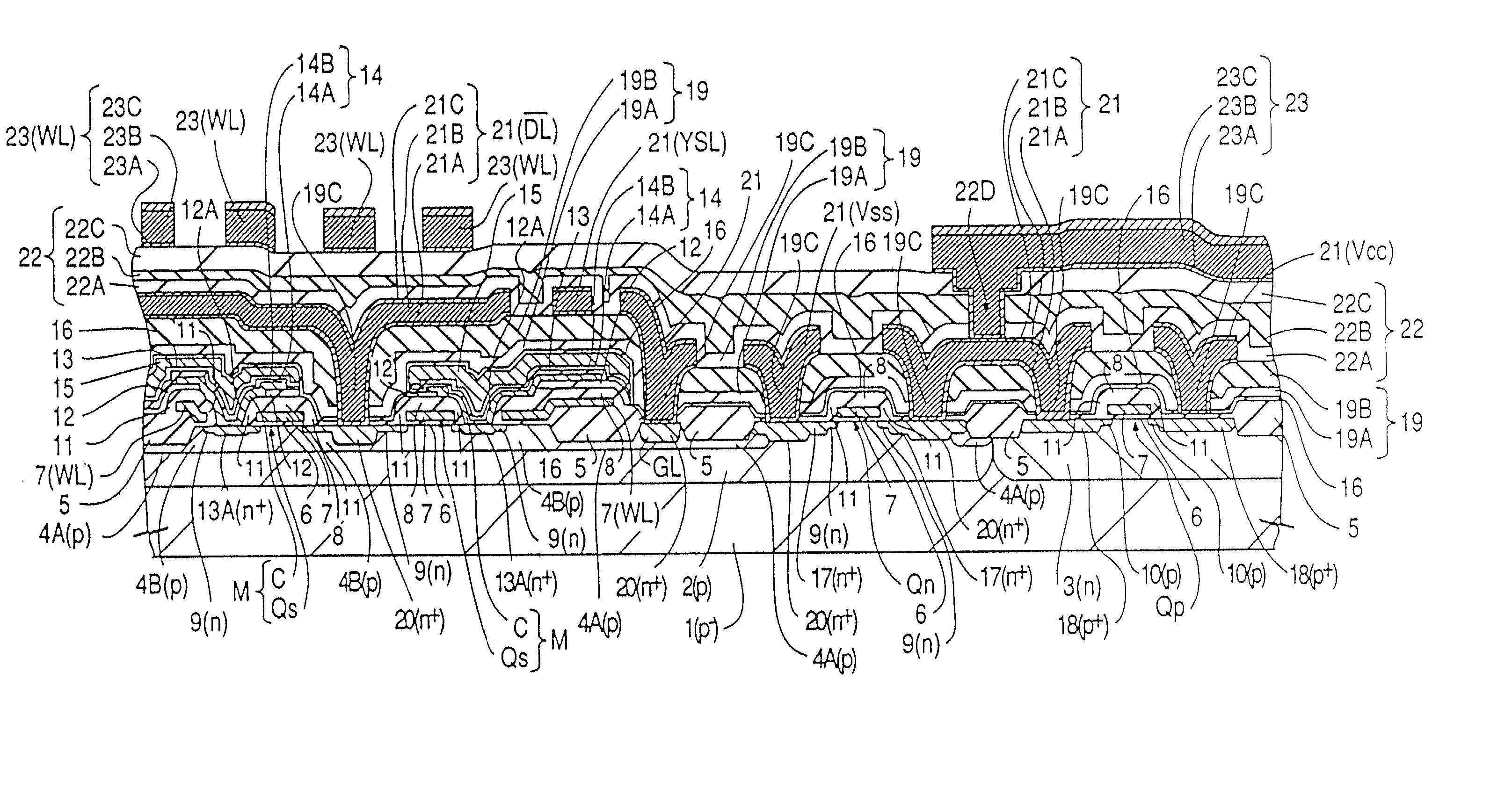
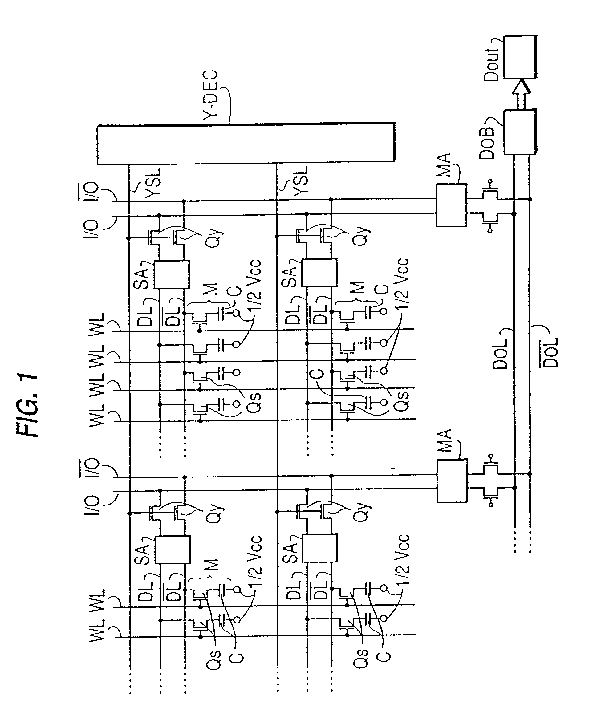
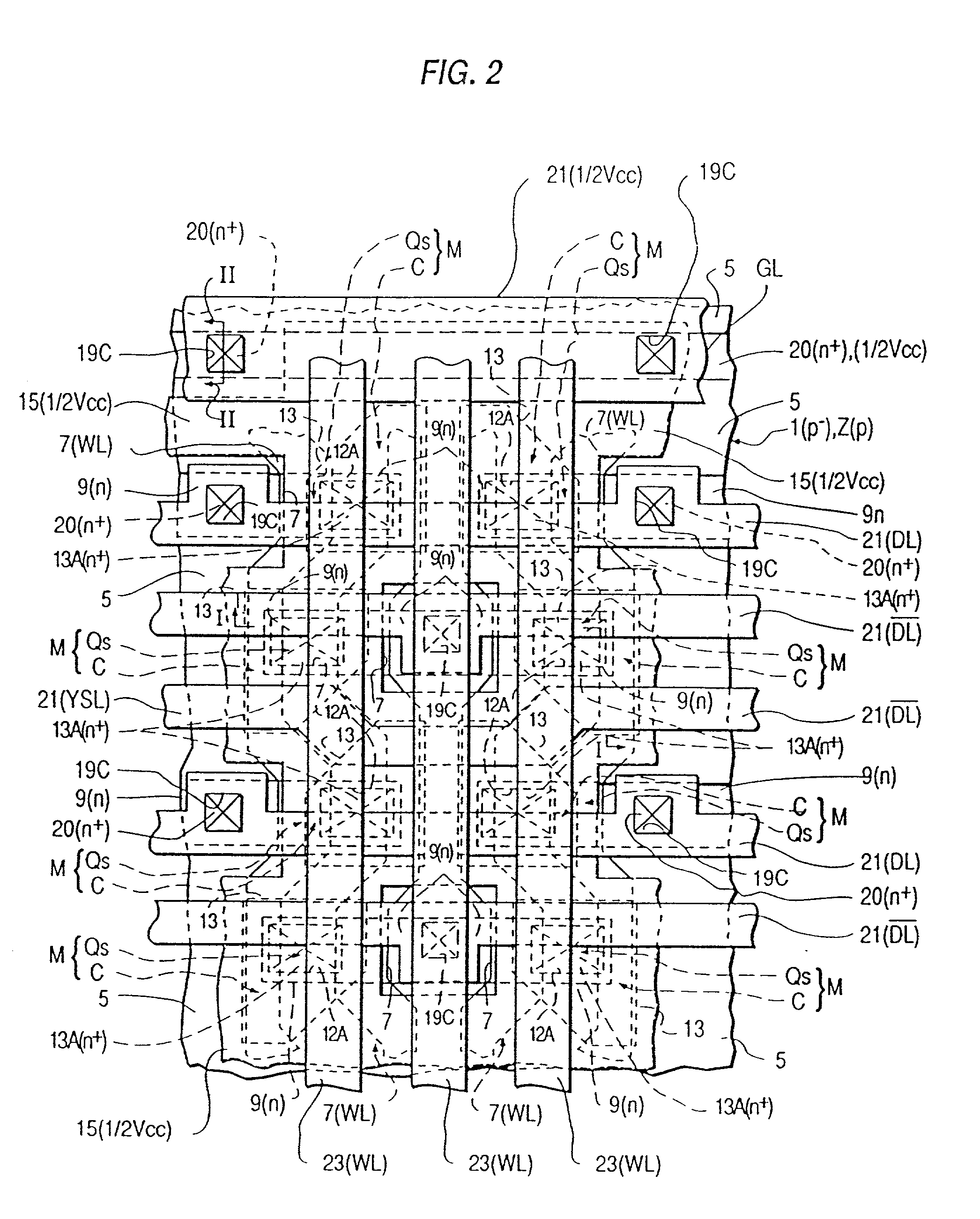
[0094] While each of the various aspects of the present invention will be described in connection with a specific embodiment, it will be understood that such description is not intended to limit the invention. On the contrary, the present invention is intended to cover all alterations, modifications and equivalents as may be included within the spirit and scope of the invention, as defined by the present claims.

[0095] The present invention, in all of its aspects, springs forth from various problems found and addressed in attempting to provide an integrated circuit semiconductor device, such as a memory device (e.g., a DRAM), formed using a semiconductor material, having increased integration density such as an integration density of at least 1 Mbit. By semiconductor material, we generally mean the semiconductor in which active regions are provided (e.g., semiconductor substrate, well region formed in a substrate, epitaxial layer, etc.). While the specific embodiment is discussed in ...


PUM


Abstract

A semiconductor integrated circuit device having a switching MISFET, and a capacitor element formed over the semiconductor substrate, such as a DRAM, is disclosed. In a first aspect of the present invention, the impurity concentration of the semiconductor region of the switching MISFET to which the capacitor element is connected is less than the impurity concentration of semiconductor regions of MISFETs of peripheral circuitry. In a second aspect, the Y-select signal line overlaps the lower electrode layer of the capacitor element. In a third aspect, a potential barrier layer, provided at least under the semiconductor region of the switching MISFET to which the capacitor element is connected, is formed by diffusion of an impurity for a channel stopper region. In a fourth aspect, the dielectric film of the capacitor element is co-extensive with the capacitor electrode layer over it. In a fifth aspect, the capacitor dielectric film is a silicon nitride film having a silicon oxide layer thereon, the silicon oxide layer being formed by oxidizing a surface layer of the silicon nitride under high pressure. In sixth and seventh aspects, wiring is provided. In the sixth aspect, an aluminum wiring layer and a protective (and / or barrier) layer are formed by sputtering in the same vacuum sputtering chamber without breaking the vacuum between forming the layers; in the seventh aspect, a refractory metal, or a refractory metal suicide QSi.sub.x, where Q is a refractory metal and 0<x<2, is used as a protective layer, for an aluminum wiring containing an added element (e.g., Cu) to prevent migration.

Description

[0001] This application is a Continuation application of application Ser. No. 08 / 620,867, filed Mar. 25, 1996, the contents of which are incorporated herein by reference in their entirety, which application Ser. No. 08 / 620,867 is a Continuation application of Ser. No. 08 / 254,562, filed Jun. 6, 1994, which is a Divisional application of Ser. No. 07 / 894,351, filed Jun. 4, 1992, which is a Divisional application of Ser. No. 07 / 246,514, filed Sep. 19, 1988.BACKGROUND OF THE INVENTION[0002] The present invention relates to a semiconductor integrated circuit device, particularly a semiconductor integrated circuit memory device, and more particularly to structure which is effective when applied to a semiconductor integrated circuit device having dynamic random access memories (DRAMs), and methods for the production thereof. The present invention is further directed to a semiconductor integrated circuit device having a capacitor element, particularly a semiconductor integrated circuit memor...

Claims


Application Information

Patent Timeline
Patent Type & Authority Applications(United States)
IPC IPC(8): H01L27/10H01L21/8242H01L27/105H01L27/108
CPCH01L27/105H01L27/10808H10B12/31H10B12/00
Inventor MURATA, JUNTADAKI, YOSHITAKAASANO, ISAMUHORIUCHI, MITSUAKISUGIURA, JUNKANEKO, HIROKOSHIMIZU, SHINJIHIRAIWA, ATSUSHIOGISHI, HIDETSUGUSAGAWA, MASAKAZUOZAWA, MASAMISEKIGUCHI, TOSHIHIRO
Owner HITACHI LTD
Learn More