Micro-fluidic chip, detection system based on micro-fluidic chip and detection method of bacteria
A microfluidic chip and bacteria technology, applied in measurement devices, instruments, scientific instruments, etc., can solve the problems of complex signal detection instruments, poor reproducibility of electrochemical methods, low sensitivity of colorimetric methods and fluorescence methods, etc. Strong light, low reagent consumption, good biocompatibility
- Summary
- Abstract
- Description
- Claims
- Application Information
AI Technical Summary
Problems solved by technology
Method used
Image
Examples
Embodiment 1
[0065] Example 1: Structure of microfluidic chip
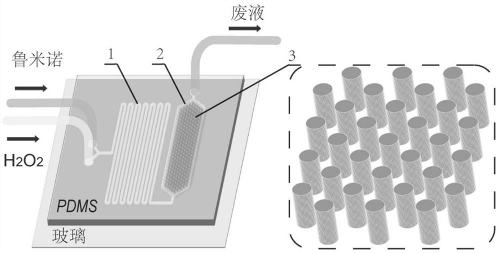
[0066] This embodiment provides a microfluidic chip, the three-dimensional structure of which is as follows: figure 1 shown. The microfluidic chip is composed of a bonded substrate and a cover sheet. In this embodiment, the material of the substrate is glass, and the material of the cover is polydimethylsiloxane (PDMS). The cover sheet is provided with a serpentine mixing microchannel 1 and a boat-shaped reaction microchannel 2, and the micropillar arrays 3 are evenly distributed in the boat-shaped reaction microchannel 2. The boat-shaped reaction microchannel 2 includes two bows and a hull between the two bows, one bow is used as an inlet, and the other is used as an outlet. The mixing microchannel includes 2 inlets and 1 outlet, and the 2 inlets are used as the inlets of luminol and hydrogen peroxide respectively. The outlet of the mixing microchannel is connected to the bow inlet of the boat-shaped reaction microchannel...
Embodiment 2
[0071] Example 2: Preparation of microfluidic chip
[0072] The silicon wafer was firstly ultrasonicated with ethanol for 5 minutes, and then deionized water for 5 minutes, and then heated on a heating plate for 120 minutes after performing three times of ultrasonication.
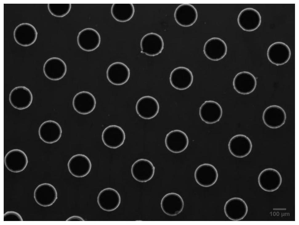
[0073] A thin layer of SU-82050 negative photoresist was spin-coated on the silicon wafer, and the thickness of the adhesive layer was about 50 μm by controlling the rotating speed. will have figure 2 The mask of the structure is bonded to the silicon wafer, the ultraviolet light passes through the photomask to expose the photoresist, and the unexposed part is dissolved with a developer. The raised SU-8 structure on the silicon wafer surface serves as a positive mold for the PDMS cover slip. The silicon positive mold was then silanized overnight.
[0074] The PDMS prepolymer (monomer / curing agent = 10 / 1 mixed) is poured on the silicon positive mold and vacuum degassed, then placed in a 75°C oven to cure...
Embodiment 3
[0080] Embodiment 3: detection system based on microfluidic chip
[0081] This embodiment provides a detection system based on a microfluidic chip, such as Figure 4 As shown, it includes the microfluidic chip d described in Example 1, a sampling unit and a detection and analysis unit, and the sampling unit communicates with the inlet of the mixing microchannel of the microfluidic chip.
[0082] In a specific embodiment, the detection and analysis unit includes a PMT detector f and an ultra-weak chemiluminescence analyzer g. The size of the microfluidic chip matches the card slot in the box of the PMT detector (25*25mm), and after it is placed, the boat-shaped reaction microchannel just matches the position of the light inlet of the PMT detector, and the chemical produced The luminescence signal was collected by PMT and analyzed by ultra-weak chemiluminescence analyzer g.
[0083] The sampling unit includes a micro-syringe pump a, a PTFE catheter c and a syringe b. The micro...
PUM
| Property | Measurement | Unit |
|---|---|---|
| width | aaaaa | aaaaa |
| depth | aaaaa | aaaaa |
| length | aaaaa | aaaaa |
Abstract
Description
Claims
Application Information
 - R&D
- Intellectual Property
- Life Sciences
- Materials
- Tech Scout
- Unparalleled Data Quality
- Higher Quality Content
- 60% Fewer Hallucinations
Browse by: Latest US Patents, China's latest patents, Technical Efficacy Thesaurus, Application Domain, Technology Topic, Popular Technical Reports.
© 2025 PatSnap. All rights reserved.Legal|Privacy policy|Modern Slavery Act Transparency Statement|Sitemap|About US| Contact US: help@patsnap.com


