
Surface coating cutting tool

A cutting tool and surface coating technology, applied in the field of surface coating cutting tools, can solve the problems of sufficient chipping resistance, poor toughness, peeling, etc., and achieve the effect of suppressing chipping and excellent wear resistance

Active Publication Date: 2014-02-12
MITSUBISHI MATERIALS CORP
View PDF13 Cites 13 Cited by
  • Summary
  • Abstract
  • Description
  • Claims
  • Application Information

AI Technical Summary

Problems solved by technology

[0017] However, in the coated tools described in the above-mentioned Patent Documents 1 and 2, the film formed by the physical vapor deposition method is composed of (Ti 1-X Al X ) The hard coating layer composed of N layer cannot increase the Al content X in the film, so it cannot be said that the chipping resistance is sufficient when it is used for high-speed interrupted cutting of alloy steel, for example.
[0018] On the other hand, the (Ti 1-X Al X ) The N layer can increase the Al content X, and can form a cubic crystal structure, so that a hard coating layer with a specified hardness and excellent wear resistance can be obtained, but the adhesion strength with the substrate is not sufficient, and due to the toughness Poor, when used as a clad tool for high-speed interrupted cutting of alloy steel, abnormal damage such as chipping, chipping, and peeling is prone to occur, and satisfactory cutting performance cannot be said to be exerted
[0019] Moreover, when the coated tool described in the above-mentioned Patent Document 5 is used for continuous cutting of carbon steel, it shows a certain degree of adhesion and wear resistance. During high-speed interrupted cutting, etc., due to chipping, chipping, peeling, etc., satisfactory cutting performance cannot be exerted in long-term use.

Method used


Image

  • Surface coating cutting tool
  • Surface coating cutting tool
  • Surface coating cutting tool

Examples


Embodiment 1

[0072] As raw material powders, WC powder, TiC powder, ZrC powder, TaC powder, NbC powder, Cr 3 C 2 powder and Co powder, these raw material powders were blended into the compounding composition shown in Table 1, and paraffin wax was further added and ball milled in acetone for 24 hours, dried under reduced pressure, and then pressed into a green compact of a predetermined shape with a pressure of 98 MPa. In a vacuum of 5Pa, vacuum sinter the compact under the condition of maintaining a specified temperature in the range of 1370-1470°C for 1 hour. After sintering, WC-based cemented carbide substrates with the blade shape of ISO standard SEEN1203AFSN are manufactured respectively. A~D.

[0073] In addition, TiCN (TiC / TiN=50 / 50 in mass ratio) powder, Mo 2 C powder, ZrC powder, NbC powder, TaC powder, WC powder, Co powder, and Ni powder. These raw material powders were blended into the compounding composition shown in Table 2, wet mixed with a ball mill for 24 hours, dried, and...

Embodiment 2

[0121] As raw material powders, cBN powder, TiN powder, TiCN powder, TiC powder, Al powder, Al 2 o 3 Powder, these raw material powders were compounded into the compounding composition shown in Table 8, wet-mixed with a ball mill for 80 hours and dried, and then press-molded with a pressure of 120MPa to form a green compact with a size of diameter: 50mm×thickness: 1.5mm, and then The compact was sintered in a vacuum atmosphere of 1 Pa at a specified temperature in the range of 900 to 1300°C for 60 minutes to obtain a pre-sintered body for cutting blades. : 8% by mass, WC: remaining composition, diameter: 50mm×thickness: 2mm WC-based cemented carbide supporting sheets overlapped, put into a normal ultra-high pressure sintering device, under normal conditions, that is, at a pressure of 4GPa, 1200 ~ 1400 ℃ at a specified temperature in the temperature range of 0.8 hours to carry out ultra-high pressure sintering, after sintering, use a diamond grinding wheel to grind the upper a...


PUM

PropertyMeasurementUnit
The average particle sizeaaaaaaaaaa

Abstract

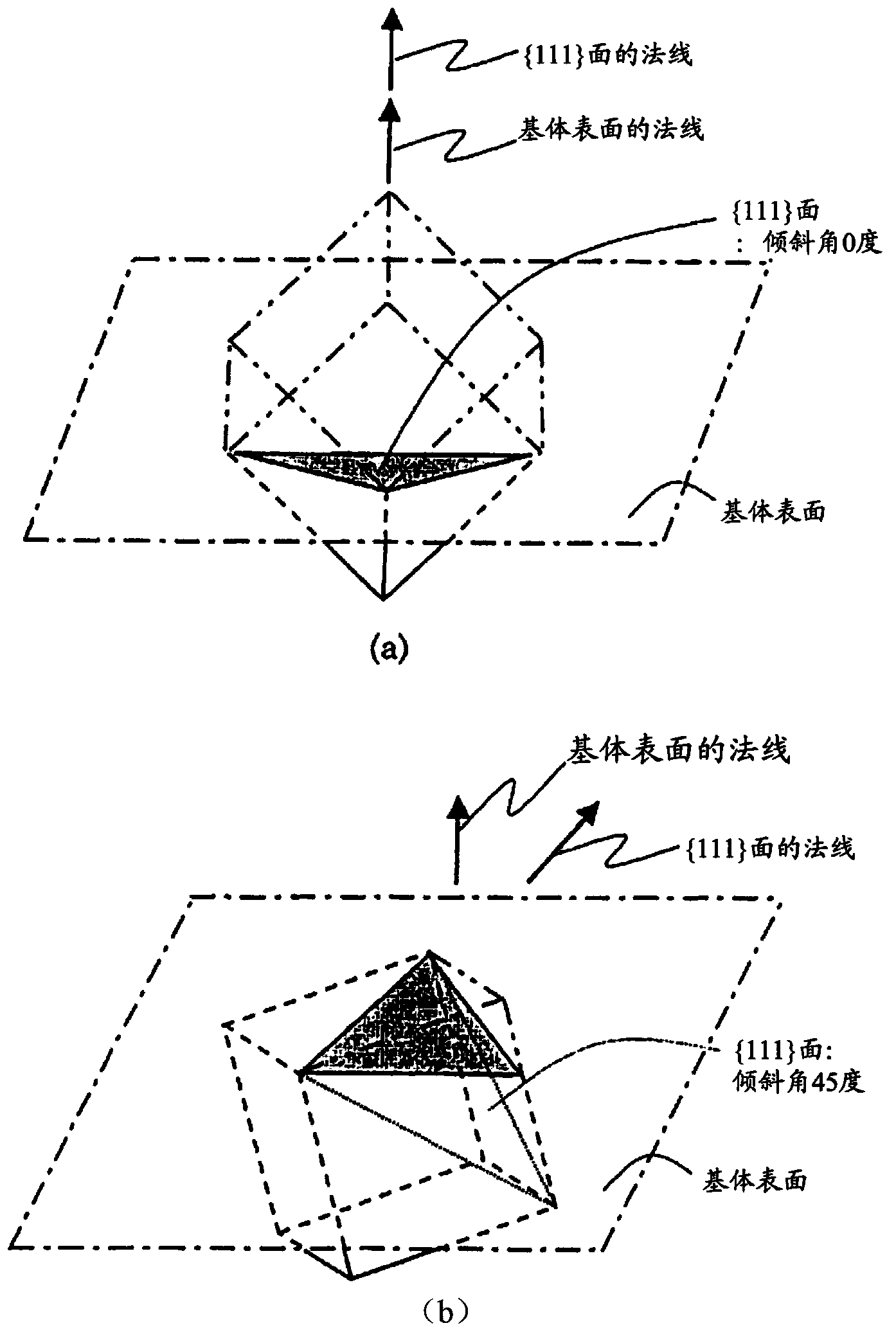
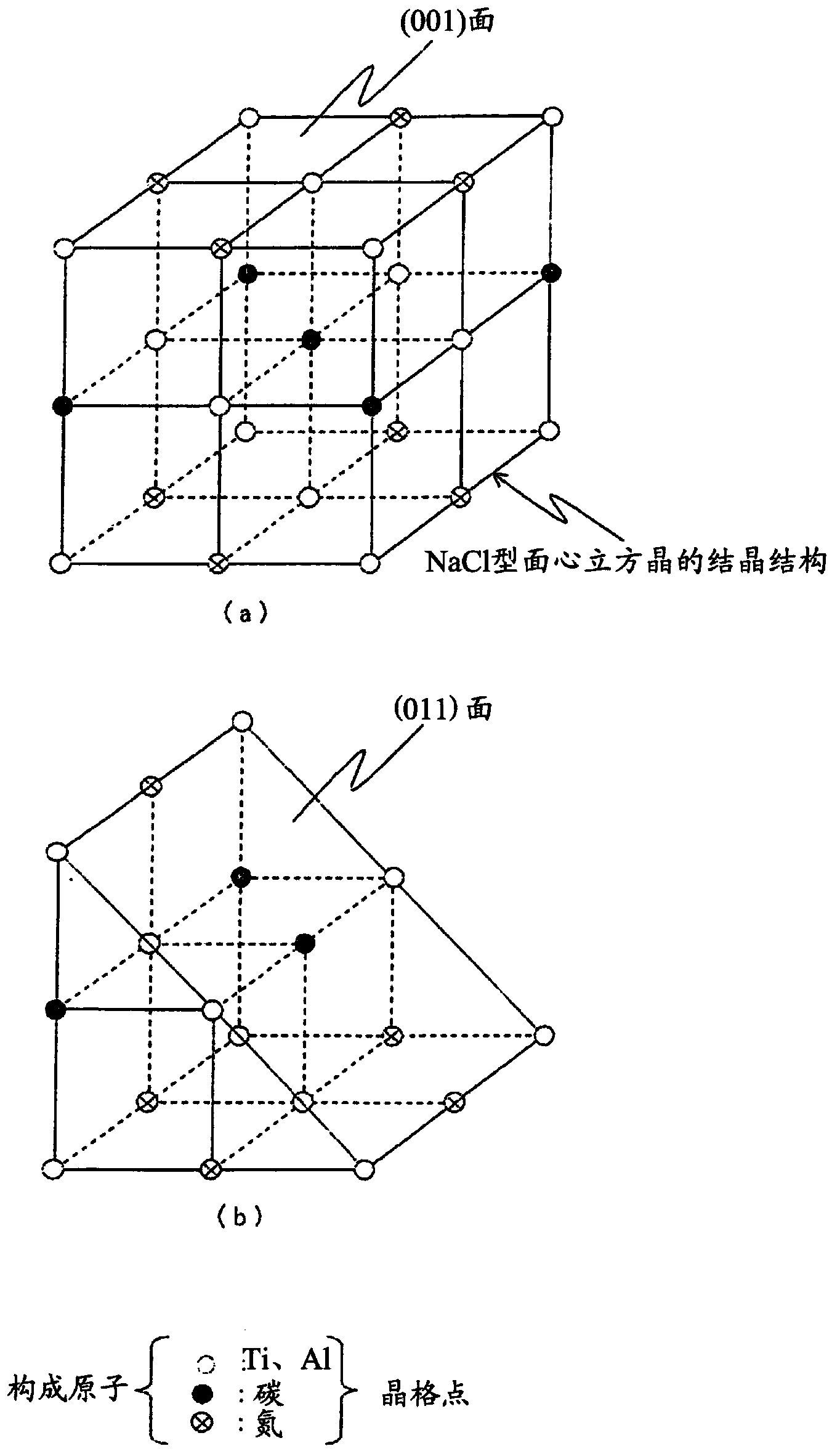
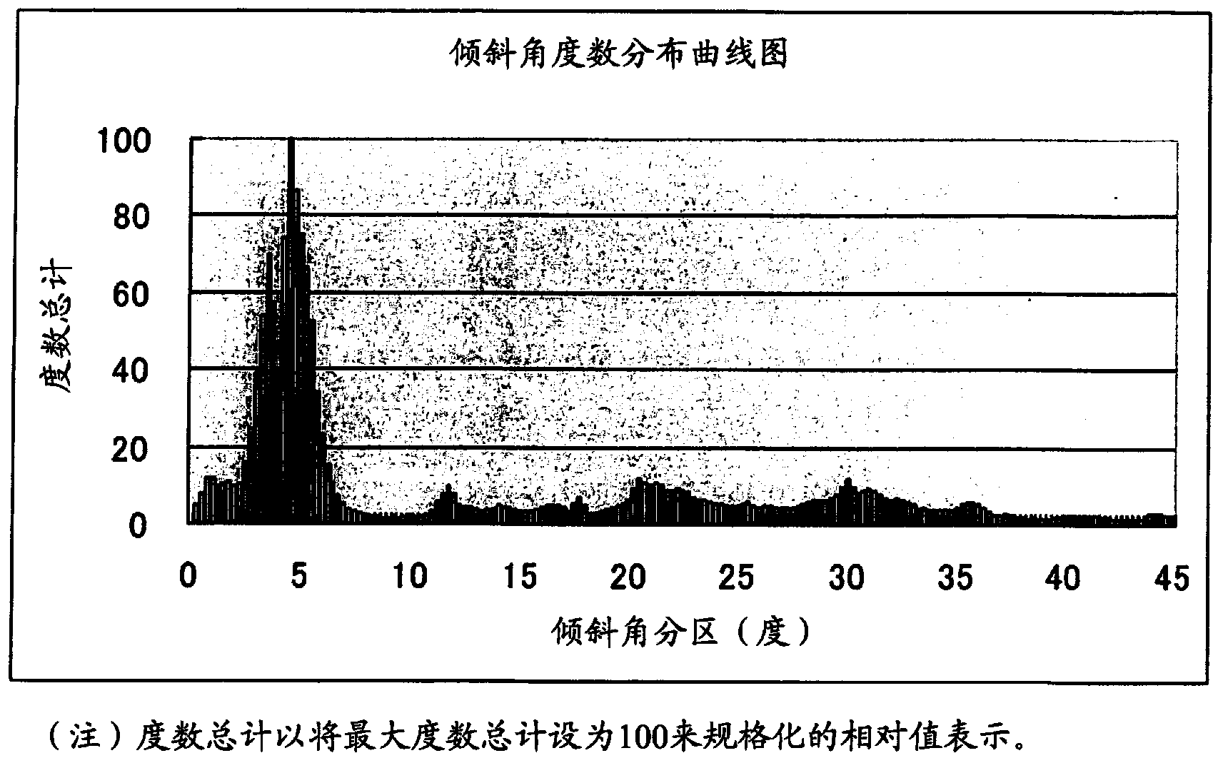
The present invention provides a surface coating cutting tool with a hard coating layer, wherein the hard coating layer plays an excellent flaking-proof role in the high-speed intermittent cutting machining operation on alloy steel materials and the like. According to the technical scheme of the surface coating cutting tool, the surface of a substrate is coated with a hard coating layer which is a (Ti1-XAlX) (CYN1-Y) layer of a cubic crystal structure and evaporated through the chemical vapor deposition process with Al(CH3)3 as one component of reaction gases, wherein the atomic ratios of X and Y are as follows: 0.55 <= X <= 0.95, and 0.0005 <= Y <= 0.005. In the hard coating layer, among the inclined angle degree distribution of the inclined angles formed by relative relationship between the normal of the {111} surface of a measured crystal particle and the normal direction of the surface of the substrate, degrees in the range of 2-12 is more than 45% of the total degree, and moreover, in the shared lattice point distribution curve graph of the component atom of the hard coating layer, the distribution proportion of Sigma 3 at the side of the surface of the substrate is less than 20%, on the other hand, Sigma 3 at the side of the surface of the coating layer has the highest peak valve and the distribution proportion of Sigma 3 is more than 50%.

Description

technical field [0001] The present invention relates to a surface-coated cutting tool (hereinafter referred to as a coated tool), in which the hard coating layer is used in high-speed intermittent cutting processing of alloy steel and the like accompanied by high heat generation and impact load acting on the cutting edge. Excellent chipping resistance. Background technique [0002] In the past, the following cladding tools are known, that is, usually made of tungsten carbide (hereinafter, represented by WC)-based cemented carbide, titanium carbonitride (hereinafter, represented by TiCN)-based cermets or cubic boron nitride (hereinafter represented by TiCN) , represented by cBN)-based ultra-high pressure sintered body (hereinafter, these are collectively referred to as the substrate) on the surface of the surface, coated with a Ti-Al composite nitride layer as a hard coating layer by physical vapor deposition, and They are known to exert excellent wear resistance. [0003] ...

Claims


Application Information

Patent Timeline
IPC IPC(8): C23C16/30
Inventor 龙冈翔五十岚诚岩崎直之山口健志长田晃
Owner MITSUBISHI MATERIALS CORP
Learn More