
Depolymerization process of conversion of organic and non-organic waste materials into useful products

a technology of organic and non-organic waste materials and depolymerization process, which is applied in the direction of chemical/physical/physical-chemical processes, waste based fuels, organic chemistry, etc., can solve the problems of large volumes of waste materials containing largely organic materials produced by the industry, significant economic and environmental pressures for members, and large volume of waste materials produced. , to achieve the effect of high energy efficiency

Active Publication Date: 2010-08-10
SYNPET TEKNOLOJI GELISTIRME
View PDF106 Cites 51 Cited by
  • Summary
  • Abstract
  • Description
  • Claims
  • Application Information

AI Technical Summary

Benefits of technology

[0081]The process of the present invention can handle and process a feedstock of mixed low-value waste materials without the need for presorting the material into pure streams. Additionally, the process of the invention can hydrolyze the oxygen-chlorine bonds in PVC and transfer metals and halides into the water. As with the hydrolysis of PVC, hydrogen ions in water combine with halide ions, e.g. Br and Cl, to produce relatively benign chemicals of use. Toxic chemicals, e.g. PCBs, PBDEs, that would otherwise leach out from SR are destroyed in the process, producing oil that is free from such contaminants and other debris. Characteristics of two batches of cracked oil products of SR are provided in the tables below. Another advantage of the present invention is its ability to handle and effectively process materials of heterogeneous size and composition. The need for particle sizing / reduction is obviated by the depolymerization step of the process, the mechanism of which will be evident from the following disclosure.
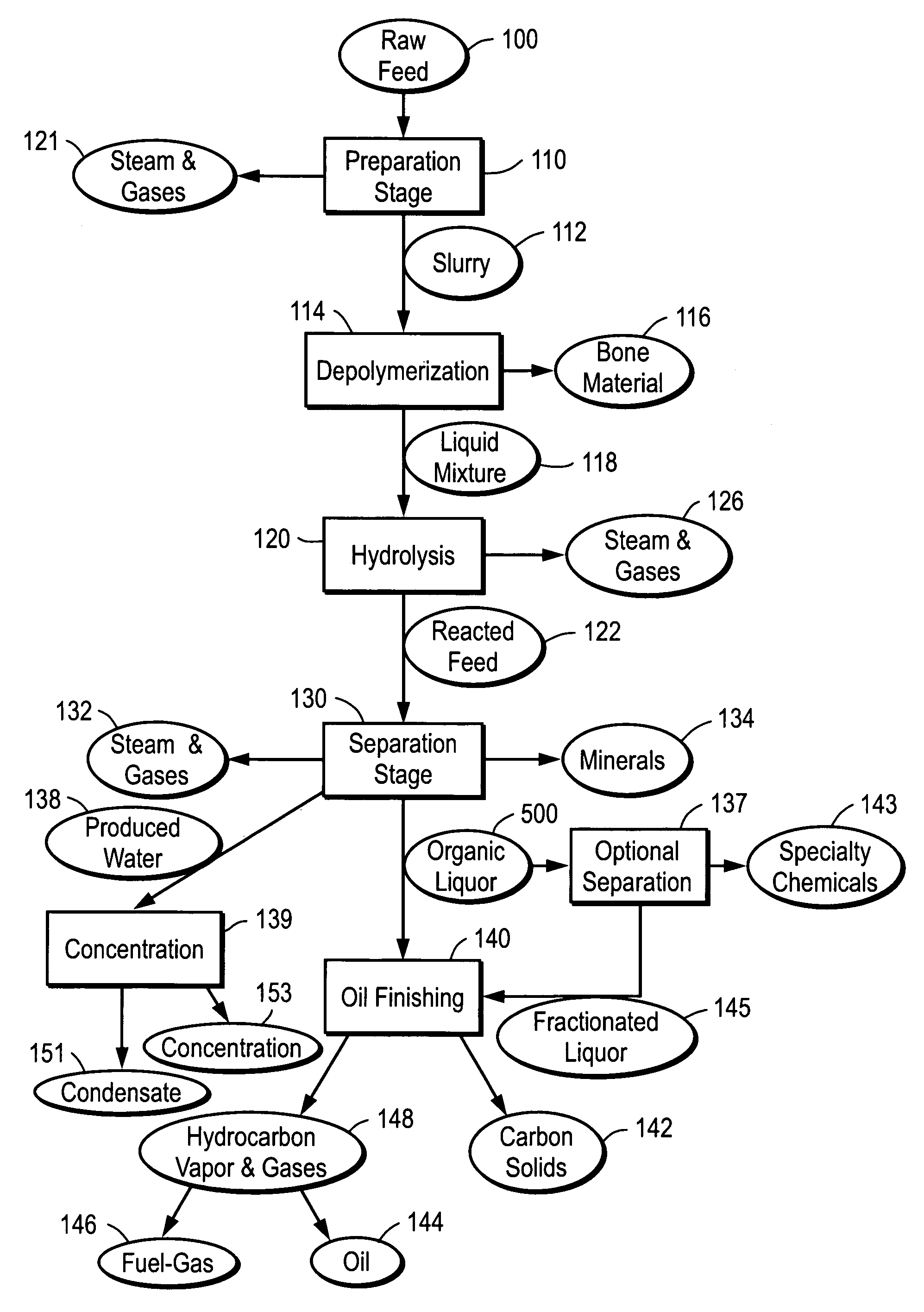
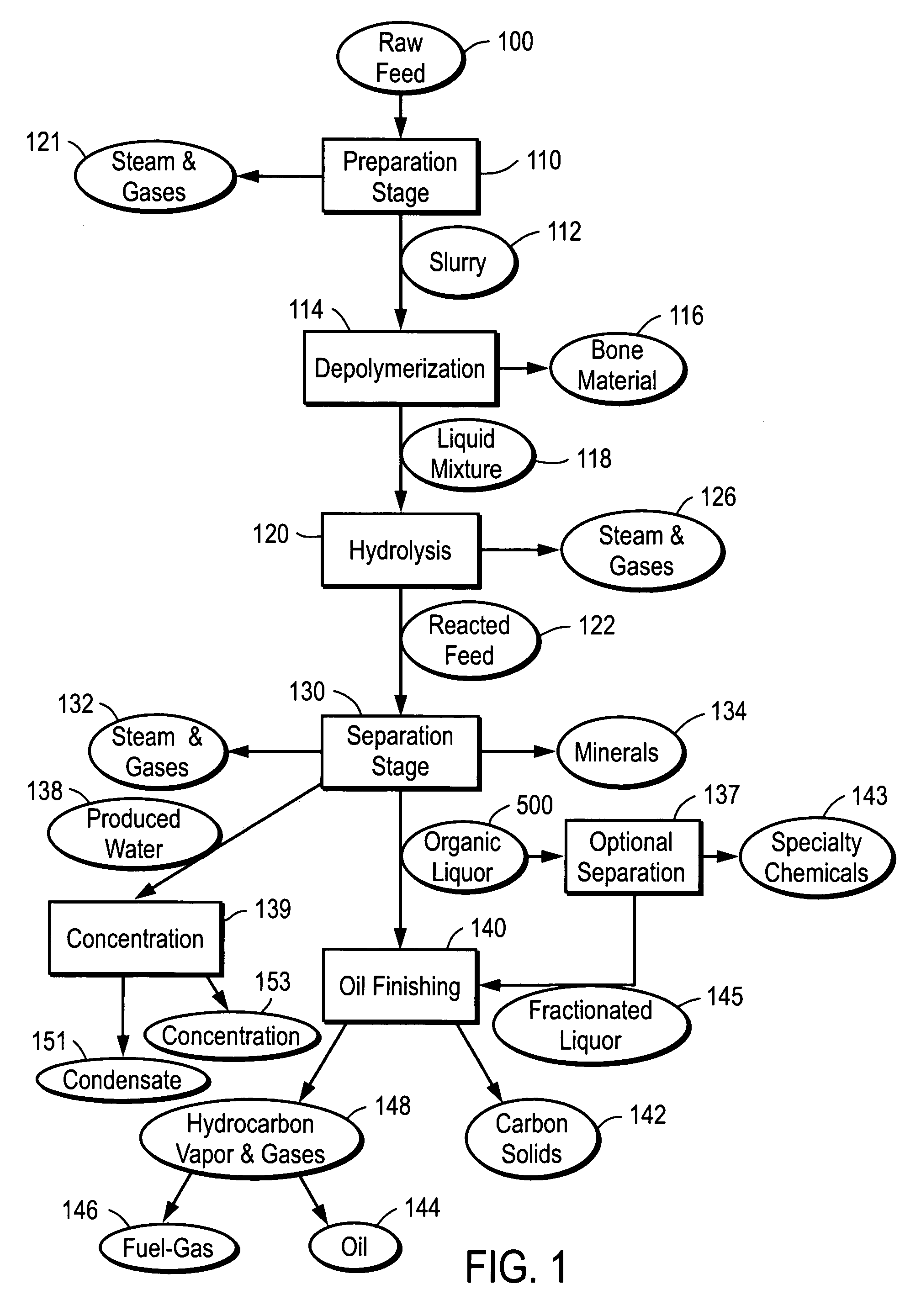
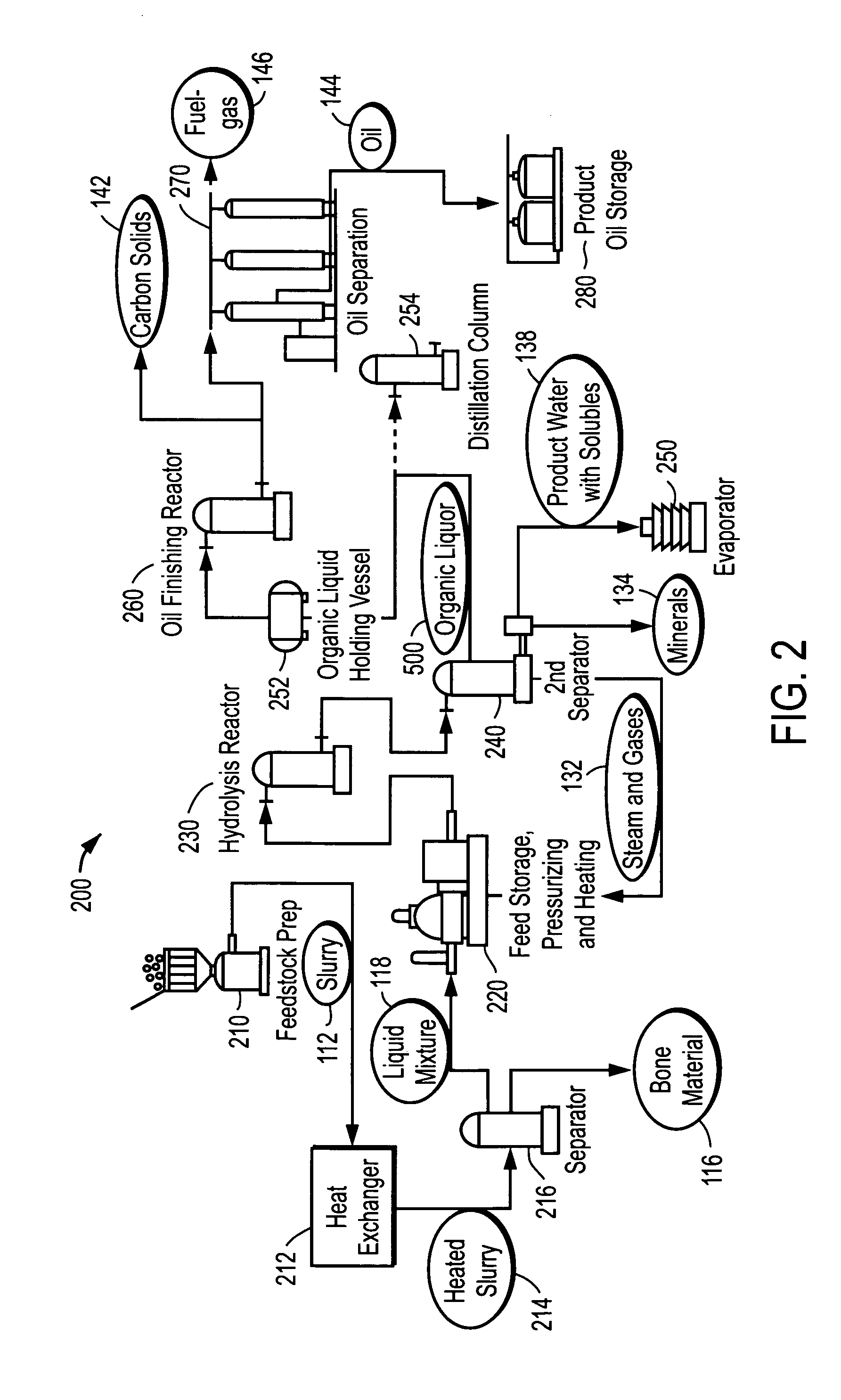
[0082]When applying the process of the present invention to SR, a portion of the produced oil is preferably recycled to the inlet to assist dissolving the SR in the incoming feedstock. A schematic of the process as applied to SR is depicted in FIG. 10. The raw feedstock is subjected to a preparation step 110, a depolymerization or “melting step,” followed by mechanical separation, whereby solids are removed from the mixture. Depolymerization reduces the organic in the solid SR to a liquid, thereby enabling the separation of metal objects and other solid organics as well as improved contact of the organic with water in the subsequent hydrolysis step. In preferred embodiments of the invention, the depolymerization occurs at temperatures in the range of about 690° F. to about 785° F., more preferably in the range of about 700° F. to about 775° F., most preferably in the range of about 720° F. to about 750° F.
[0083]The resulting mixture is then subjected to a hydrolysis step equivalent to the Hydrolysis Stage 120 described herein. Hydrolysis of chlorinated and / or brominated organics in the mixture breaks the carbon-halide bond and transfers the halide to the water phase, effectively destroying compounds such as PCBs. Hydrolysis also allows transfer of metal ions to the water phase, making the resulting oil essentially free of contamination. In preferred embodiments of the invention, the hydrolysis occurs at temperatures in the range of about 430° F. to about 510° F., more preferably in the range of about 440° F. to about 500° F., most preferably in the range of about 450° F. to about 480° F.
[0084]The reacted feed produced then undergoes a thermal and mechanical separation step. In a process similar to delayed coking, the hydrolysis oil is heated to approximately 500° C. The heat transfer to oil is rapid and isothermal and only “dry” organic oil is heated to the final temperature. The fuel oil or organic liquor 500 obtained therefrom is fed to a Oil Finishing Stage for finishing. Fuel-gas 146, carbon solids 142, or oil 144 can be produced by coking the organic liquor either on-site or at a refinery. Alternatively, a hydrocarbon oil with similar constitutents as a #4 diesel oil can be produced with minimal on-site processing.
[0085]Characteristics of two different batches of cracked oil products of the process as applied to SR are provided below.
[0086]Batch 1DistillateAPI at 60° F.40.7Distillation, ° F. IBP119 10%234 50%451 90%652 FBP691Sulfur wt %0.124Ash wt %0.003Nitrogen %<0.1BTU / lb18,622BTU / Gal127,409

Problems solved by technology

As of today, however, industries that produce huge volumes of waste materials comprising largely organic materials face enormous challenges in disposing and storing that waste, as well as putting it to maximum beneficial use.
The food processing industry continues to grow and its members face significant economic and environmental pressures to do something productive with their waste materials.
Such waste materials give rise to a number of critical problems.
The generation of greenhouse gases such as carbon dioxide and methane by landfilling, land applying, or digesting food wastes, without any other benefit, is one such problem.
More recently, the cost of warehousing unusable byproducts in many areas is growing in significance.
Dwindling federal grants for construction of new and upgraded POTWs also mean that this option is less appealing.
Bioaccumulation of persistent chemicals such as dioxins and the potential for the spread of life threatening diseases such as Mad Cow Disease (BSE) is another threat to food processors and food consumers alike.
This threat is greatly exacerbated by refeeding food processing residues to farm animals.
Treatment of industrial waste, namely shredder residue, likewise presents another challenge.
Disposal of shredder residue is made all the more difficult by the toxic materials found therein, e.g. cadmium, lead, mercury, and other heavy metals.
Due to the limited amount of space available for landfill use and the increasing costs of hazardous waste disposal, an alternate solution is needed.
Due to the high BOD concentrations typically found in high-strength food process wastewaters with high levels of suspended solids, ammonia, and protein compounds, the food processing industry is under additional scrutiny.
For example, the generation of malodorous air emissions associated with rendering plants—that convert animal waste by heat into fats and proteins, is one such problem.
However, such schemes are rendered energy-inefficient by virtue of the amount of energy needed to achieve super-critical conditions.
Processing at super-critical conditions is also not cost-effective as it requires expensive super-alloy operating equipment.
Additionally, most schemes that use a solvent to dissolve tire material are uneconomical due to loss of some fraction of the solvent during the process and the cost associated with the make-up solvent, even in instances where solvent recovery and reuse can be practiced.
There are a number of problems associated with their use.
Once the nutritional feed materials are exhausted, the bugs can no longer sustain themselves, and they die.
One problem with the resulting material is that it still contains pathogens.
Problems with the whole process, in general, include that the holding times in the digester vessels can be as long as 17 days, and that the operating conditions are difficult to maintain.
All of the disposal technologies currently available to industries, in particular the food processing industry, have significant limitations and drawbacks that provide an incentive to search for alternative processes.
Drawbacks for land disposal include: high haulage or transport costs, significant potential for groundwater contamination from leaching, and the exposure of area residents to high concentrations of hazardous pollutants (such as pathogens in the instance of land application).
Landfills produce gas that can create air pollution concerns, including the generation of greenhouse gases.
The process is difficult to control and its performance equally difficult to verify.
Drawbacks associated with older incineration or combustion units include the need to add equipment or components to meet increasingly heightened air pollution emission standards.
It may also take longer to obtain air discharge permits for incinerators than for other technologies due to significant community concerns about incineration.
Additionally, the treatment of the waste at the exhaust means treating large volumes of gas so that very large plant equipment is required.
The feedstock is also low in calorific value.
Some incinerators are not compatible with solid fuels or solid waste, as these materials will start to oxidize too high up in the furnace.
Conversely, high moisture content in the feedstocks is also a problem because during incineration or combustion the water is vaporized and removed—a process which requires approximately 1,000 Btu / lb of water vaporized.
This represents huge heat / energy losses to the system.
Generally, pyrolysis and gasification methods employed in the past were aimed at breaking down the waste materials in a single stage process, but a single stage has been found to offer inadequate control over purity and composition of the end products.
A pyrolyzer permits heating of the organic materials to high temperatures, ˜400-500° C., but has poor energy efficiency and gives little control over the composition of the resulting materials.
To effectuate the breakdown, pyrolyzers in the art would boil off the water using a very energy-demanding process.
However, use of a large chamber also has the unfortunate side-effects of generating significant temperature gradients throughout the chamber, resulting in uneven heating of waste materials and poor quality or impure end products.
Gasifiers also suffer from some of the same drawbacks as pyrolyzers, e.g. high energy consumption in vaporizing water content of waste material.
Products of pyrolysis and gasification methods also tend to contain unacceptably high levels of impurities.
Typically, chlorinated hydrocarbons at levels of 1-2 ppm can be tolerated in hydrocarbon oils, but neither gasification nor pyrolysis methods can guarantee such a low level with any reliability.
Furthermore, pyrolysis and gasification methods have low efficiencies, typically around 30%.
One reason for this is that the products are not optimum in terms of calorific content.
Another reason is that a single stage process cannot readily produce materials in a form from which energy can be efficiently harnessed and recycled in the process.
For example, it is difficult to capture the thermal energy in the solid products that are produced and redirect it to assist in the heating of the reaction vessel.
As detailed above, pyrolysis / gasification methods suffer in several ways.
The oil product is generally rich in undesirable high viscosity components such as tar and asphalt.
Both pyrolysis and gasification processes have poor heat transfer properties and consequently do not heat evenly.
Therefore, end products vary greatly in number with few of sufficient quantity or quality for economical recovery.
Wet feedstocks require significant energy to vaporize and represent large energy losses to the system since the water leaves as a gas in the stack.
In summary, pyrolysis / gasification has a high overall operating cost, is capital intensive, and produces some by-products of no or limited value.
However, the products of such methods still suffer from problems of contamination, from materials such as sulfur- and chlorine-containing compounds, and the need to evaporate a significant portion of the water still entails a substantial energy penalty.
Thus, prior two stage methods have been difficult to make commercially viable.

Method used


Image

  • Depolymerization process of conversion of organic and non-organic waste materials into useful products
  • Depolymerization process of conversion of organic and non-organic waste materials into useful products
  • Depolymerization process of conversion of organic and non-organic waste materials into useful products

Examples


example 1

Pilot Plant—Shredder Residue Processing

[0197]A pilot plant has been built employing apparatus and processes of the present invention.

[0198]According to one exemplary application of the pilot plant, the experimental feedstock was shredder residue. Of the 3000 lbs. of SR material received for this pilot run, 1072 lbs of dirt / fines was removed and washed with hot water, 715.5 lbs of fines-free SR were processed through the depolymerization unit, and 1212.5 lbs of fines-free SR were held back for future testing. The fines-free SR material was processed through the depolymerization unit along with 79.5 lbs of shredded tires and about 1741 lbs of used motor oil. Samples of the various products were sent out for analysis to determine the fate of heavy metals and of contaminants such as PCBs and chlorine.

[0199]Based on results from comparative sample analyses, PCBs were found to be reduced by an order of magnitude, from 35-65 ppm down to less than 2 ppm.

[0200]Thermal cracking of this hydrol...

example 2

Pilot Plant—Turkey processing

[0217]A pilot plant has been built employing apparatus and processes of the present invention. The pilot plant can handle approximately seven tons of waste per day.

[0218]According to one exemplary application of the pilot plant, the experimental feedstock was turkey processing-plant waste: feathers, bones, skin, blood, fat, viscera. An amount of 10,044 pounds of this material was put into the apparatus's Hydrolysis Stage: a 350-horsepower grinder, which turns the material into gray-brown slurry. From there, the material flowed into a series of tanks and pipes which heated and reformed the mixture.

[0219]Two hours later, a light-brown stream of steaming fine oil was produced. The oil produced by this process is very light. The longest carbon chains are C20. The produced oil is similar to a mix of half fuel oil, half gasoline.

[0220]The process of the present invention has proved to be 85% energy efficient for complex feedstocks such as turkey offal. This me...

example 3

Operating Plant

[0226]A full-sized commercial-scale installation has been constructed with additional facilities in development. At peak capacity, the plant is designed to yield over 500 barrels of oil per day, some of which can be returned to the system to generate heat for powering the system. The oil produced is a high-quality oil of the same grade as a #2 heating oil. The plant produces about 21,000 gallons of water, which is clean enough to discharge into a municipal sewage system, and is also free of pathological vectors. The plant also will make about 25 tons of minerals, concentrate and carbon.


PUM

PropertyMeasurementUnit
temperatureaaaaaaaaaa

Abstract

The present invention relates to the conversion of waste and low-value materials into useful products in reliable purities in a cost-effective and energy-efficient manner. More specifially, the invention provides processes that can handle mixed streams of various feedstocks, e.g. shredder residue, offal, animal manures, municipal sewage sludge, tires, and plastics, that otherwise have little commercial value, to useful products including gas, oil, specialty chemicals, and carbon solids. The process subjects the feedstock to heat and pressure, separates out various components, then further applies heat and pressure to one or more of those components, according to processes based on thermal or catalytic cracking. The invention further comprises an apparatus for performing a multi-stage process of converting waste materials into useful materials, and at least one oil product that arises from the process. Useful products can also be obtained or derived from materials diverted at different points of the process.

Description

CROSS-REFERENCES TO RELATED APPLICATION[0001]The present application claims priority to U.S. patent application Ser. No. 60 / 721,836, filed Sep. 28, 2005, U.S. patent application Ser. No. 60 / 727,491, filed Oct. 17, 2005, U.S. patent application Ser. No. 60 / 778,034, filed Feb. 28, 2006, U.S. patent application Ser. No. 60 / 812,275, filed Jun. 9, 2006, and U.S. patent application Ser. No. 60 / 840,207, filed Aug. 25, 2006, each of which is incorporated herein by reference in its entirety.FIELD OF THE INVENTION[0002]The present invention generally relates to the processing of waste or low-value materials to form useful products. More specifically, the invention relates to a process and apparatus for converting industrial, agricultural, and other waste or low-value materials that contain carbon-based compounds, to commercially useful products such as fuel oil, fertilizer and specialty organic chemicals. The invention also reduces the potential for environmental pollution arising from inorga...

Claims


Application Information

Patent Timeline
Patent Type & Authority Patents(United States)
IPC IPC(8): C01B7/19
CPCC10G1/02C10G1/002C10G1/10Y02E50/30
Inventor ADAMS, TERRY N.APPEL, BRIAN S.EINFELDT, CRAIG TIMOTHYFREISS, JAMES H.
Owner SYNPET TEKNOLOJI GELISTIRME
Learn More