
High spatial resolution X-ray computed tomography (CT) system

a computed tomography and high spatial resolution technology, applied in the field of high spatial resolution, can solve the problems of limited image size and anatomic coverage, many geometric distortions, and none of them are completely satisfactory

Inactive Publication Date: 2006-08-29
RGT UNIV OF MICHIGAN
View PDF58 Cites 197 Cited by
  • Summary
  • Abstract
  • Description
  • Claims
  • Application Information

AI Technical Summary

Benefits of technology

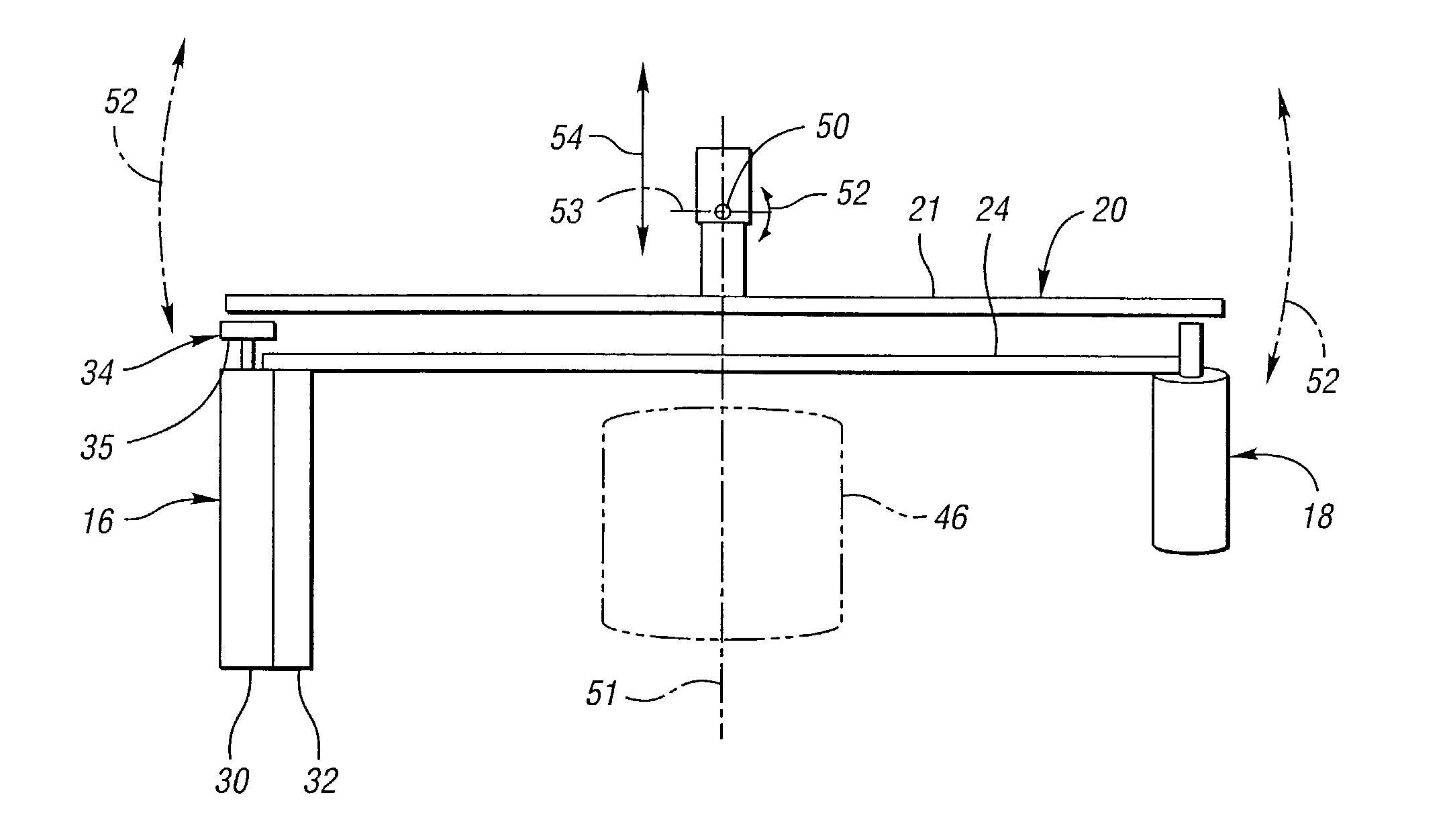
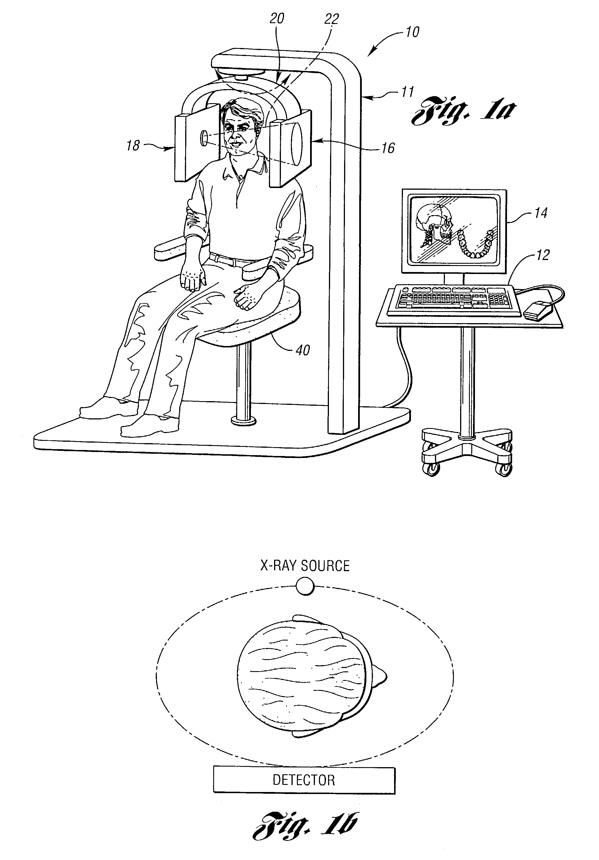
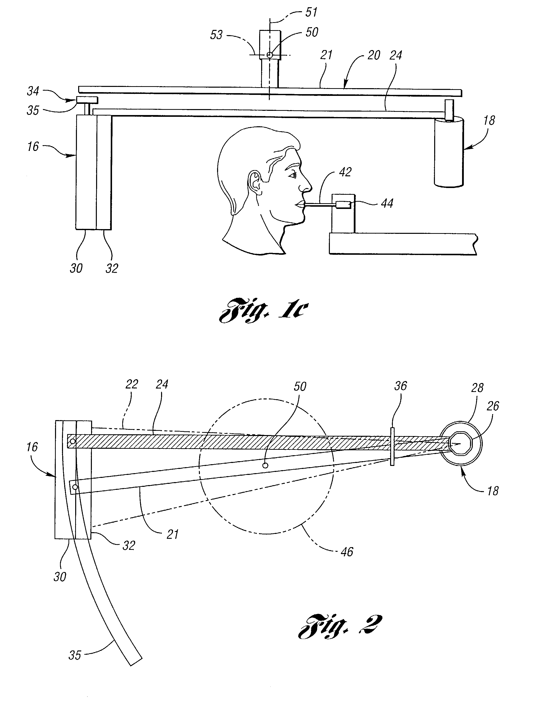
The present invention provides an improved high spatial resolution X-ray computed tomography (CT) system for dentomaxillofacial applications. The system includes a support structure with a gantry mounted to rotate about a vertical axis of rotation and a first assembly with an X-ray source and a second assembly with a planar X-ray detector. The detector is positioned between the X-ray source and the body part to be scanned. The system can generate output data representative of an area of the detector on which an X-ray beam impinges and process the output data to obtain an image of the body part. The system can also include a scatter rejection collimator and a device for controlling position of the source collimator based on the detector position. The detector can include a converter for converting X-ray radiation into visible light and a hydrogenated amorphous silicon detector array. The system can also include means for correcting for body part motion and stabilizing motion of the head. The system can provide high-quality images for dental implant pre-operative site assessment and post-operative assessment of failed implants, as well as for other dentomaxillofacial applications.

Problems solved by technology

A number of imaging modalities have been used over the years, but they all have limitations and none are completely satisfactory.
Periapical radiography has enough resolution to depict trabecular bone pattern and the floor of the maxillary sinuses, but the images are limited in size and anatomic coverage and often suffer from geometric distortion.
In addition, periapical radiographs are only two-dimensional images and do not provide information about the third, bucco-lingual, dimension.
However, there are a large number of disadvantages to this technique that limit its usefulness for implant site assessment.
The two primary problems are lack of information in the bucco-lingual plane and variability of the degree of magnification in different parts of the image due to changing distance between the rotational center, jaw structures, and film as the X-ray beam rotates around the head.
Minor errors in positioning the patient's head in the machine can also exaggerate the degree of enlargement variability, particularly in the horizontal direction.
Although dentists frequently try to overcome these magnification problems by having the patient wear a surgical stent with metal markers of a known size during the examination, this device is not adequate to solve all distortion errors.
Conventional tomographs, however, have been reported not to be of diagnostic quality sufficient to allow identification of the canal in as many as 20% of cases.
This is primarily due to the unavoidable blur that is inherent in the method, although some canals are poorly corticated and thus would be difficult to visualize with any technique.
Another very important disadvantage of conventional tomography is that it is usually necessary to acquire multiple slices to ensure that the region of diagnostic interest is sampled adequately.
Because each slice is acquired successively, the process is time-consuming and laborious, thus expensive, and it exposes the patient to a radiation dose that can be high, depending on the number of slices obtained.
Conventional CT has its drawbacks, however.
First, with its merely 2-D reformatted images, it may not clearly depict the inferior alveolar canal.
Second, it is time-consuming: conventional CT requires more than 20 minutes to get all the axial slices for a dental implant study.
With such a long scanning time, patient fatigue and patient swallowing start blurring the image.
Third, conventional CT exposes the patient to a high radiation dose.
Fourth, it is expensive.
Fifth, it suffers from poor resolution, especially in the z-direction.
Sixth, metal streak artifacts can occur in the presence of metallic dental restorations, requiring judicious selection of scan orientation and boundaries to minimize its occurrence.
However, the use of spiral CT in dentistry is hampered by its high cost and radiation dose, low spatial resolution in axial direction, and metal streak artifacts.
The use of TACT in implantology has been suggested, but no controlled studies have yet been performed.
This adds to the complexity of operating the instrument.
Second, it uses CCD sensors of a low contrast resolution.
In this context, the term “partial CT scan” refers to a cone-beam CT scan using a circular orbit, which, in addition to having the usual cone-beam incompleteness problem (i.e., a circular orbit does not satisfy Tuy's completeness conditions), is more incomplete in the sense that the data is insufficient for quantitatively reconstructing 3-D cross-sectional images to the use of a detector and scan geometry that do not measure all necessary rays through the object.
However, the applicability of Ortho-CT in implant planning is limited for four reasons.
Second, its contrast resolution is so low that Ortho-CT is incapable of discriminating soft tissue.
This is a consequence of its use of incomplete data.
Fourth, although its behavior in the presence of metal fillings has not been reported on, it is expected that it suffers from metal streak artifacts.
It can display the mesial and distal aspects of the implant site, but it provides little information about the facial and lingual aspects of the implant site because of the obscuring effects of the radiopaque implant material.
Its other major limitations include the subjective interpretation of the radiographic image, lack of sensitivity, and the inability to quantify bone mass.
The exposure factors and processing parameters that affect density and contrast must be consistent between the two scans and the projection geometry must be duplicated as nearly as possible All this makes the method laborious and inefficient, especially when the medium is film, which is often the case.
Finally, it cannot overcome the obscuring effects of a metal implant sufficiently to allow reliable detection of facial and lingual bone loss at implant sites.
However, tomography of the TMJ is technically demanding because the imaging protocol must be customized for each patient due to the variability of condylar angles.
Images made with linear-motion machines may also be suboptimal due to streaking artifacts and incomplete blurring of adjacent structures.
The use of computed tomography for TMJ imaging has generally been reserved for complex cases as a result of its relatively high cost and high radiation dose.
Evaluation of articular disk position and function is usually performed with magnetic resonance imaging or arthrotomography, again both expensive techniques.
Another important problem in dentistry is the determination of the location and displacement of facial fractures in patients who have suffered trauma to the maxillofacial region.
Conventional radiography is unsuitable for the task because it requires multiple scans to obtain all the views that are necessary for evaluation.
Even with a series of radiographs, it is sometimes difficult to detect subtle fractures.
However, the use of spiral CT for detecting facial fractures has drawbacks.
It is costly and it exposes the patient to a high radiation dose.
It also suffers from metal streak artifacts, which can result in misleading scans of the facial complex.
While conventional radiography produces adequate bone images, it provides little information regarding soft tissues as a result of the inability of film-screen systems to record X-ray attenuation differences of less than 2%.
Although CT has proven superior in many aspects to other modalities in this application, its use has been limited by three factors: cost, radiation dose and metal streak artifacts.
In addition, the spatial resolution available in current CT scanners, which are designed primarily for full-body imaging, may not be optimal for lesions in the head and neck.
MRI, however, is more expensive than CT, and requires a longer time to obtain a scan.
To date, there is no general consensus about which imaging technique is optimal for use in diagnosis of lesions in the head.
Surgery of craniofacial deformities is a complex task that requires careful preoperative planning and specific, detailed information on patient's pathology and anatomy.
However, facial reconstructive surgery presents a three-dimensional problem of anatomical rearrangement and cannot be effectively planned using two-dimensional images.
Morever, some facial and skeletal anomalies, specifically those involving facial asymmetry, are not amenable to analysis using only two-dimensional images.
However, both are expensive.
In addition, CT suffers from metal streak artifacts and exposes the patient to a high radiation dose while MRI is not particularly useful for examining bony structures.
Ortho-CT is a vertically oriented device that acquires a partial CT scan, and while spatial resolution is adequate, the device suffers from artifacts due to the incomplete nature of the scan and does not produce quantitatively accurate estimates of attenuation (necessary for assessing bone quality).
The TomCAT uses an image intensifier and CCD camera for the detector—a combination that has relatively poor dynamic range (reducing quantitative accuracy) and also suffers from spatial distortions.
Although images reconstructed from TomCAT have spatial resolution similar to conventional general-purpose CT instruments, contrast resolution is quite poor and images appear to suffer from a great deal of X-ray scatter (and perhaps veiling glare from the image intensifier).

Method used


Image

  • High spatial resolution X-ray computed tomography (CT) system
  • High spatial resolution X-ray computed tomography (CT) system
  • High spatial resolution X-ray computed tomography (CT) system

Examples


Embodiment Construction

[0089]A system of the present invention possess a wide spectrum of properties to be used effectively both in implantology and for the applications described. The properties are summarized below in Table 1.

[0090]

TABLE 1 1.High contrast-resolution for both bone and soft tissue; 2.High spatial resolution in X, Y, and Z directions; 3.Low radiation dose; 4.Metal streak artifacts removal; 5.Quantification of soft tissue andbone densities and their changes; 6.Full 3-D capabilities; 7.Ability to generate axial, coronal, sagittal, andoblique planes images; 8.Ability to produce undistorted images with linearmeasurements preserved; 9.High scanning speed to avoid body movement artifacts;10.Relatively inexpensive; and11.Easy to use.

None of the previous dentomaxillofacial imaging modalities possesses all these properties, and the practitioner has historically been face with various trade-offs in the decision as to which modality to use.

[0091]The new system features all the properties from Table 1...


PUM

PropertyMeasurementUnit
anglesaaaaaaaaaa
sizesaaaaaaaaaa
computed tomographyaaaaaaaaaa

Abstract

A high spatial resolution X-ray computed tomography (CT) system is provided. The system includes a support structure including a gantry mounted to rotate about a vertical axis of rotation. The system further includes a first assembly including an X-ray source mounted on the gantry to rotate therewith for generating a cone X-ray beam and a second assembly including a planar X-ray detector mounted on the gantry to rotate therewith. The detector is spaced from the source on the gantry for enabling a human or other animal body part to be interposed therebetween so as to be scanned by the X-ray beam to obtain a complete CT scan and generating output data representative thereof. The output data is a two-dimensional electronic representation of an area of the detector on which an X-ray beam impinges. A data processor processes the output data to obtain an image of the body part.

Description

STATEMENT REGARDING FEDERALLY SPONSORED RESEARCH OR DEVELOPMENT[0001]This invention was made with Government support under NIH Grant No. CA 65637. The Government has certain rights in the invention.CROSS-REFERENCE TO RELATED APPLICATION[0002]This application is related to co-pending application entitle “Method, Processor and Computed Tomography (CT) Machine for Generating Images Utilizing High and Low Sensitivity Data Collected From A Flat Panel Detector Having an Extended Dynamic Range”, filed May 29, 2002 and having U.S. Ser. No. 10 / 157,282.BACKGROUND OF THE INVENTION[0003]1. Field of the Invention[0004]This invention relates to high spatial resolution, X-ray computed tomography (ct) systems.[0005]2. Background Art[0006]The current state of imaging modalities used in these areas of dentomaxillofacial practice, with a particular emphasis on implantology, is described in the following subsections.Implantology: Pre-operative and Post-operative Imaging[0007]The use of dental implants ...

Claims


Application Information

Patent Timeline
Patent Type & Authority Patents(United States)
IPC IPC(8): G01N23/00A61B6/06A61B6/51
CPCA61B6/14A61B6/4233A61B6/482A61B6/583A61B6/06A61B6/4035A61B6/4291A61B6/027A61B6/4441A61B6/51
Inventor CLINTHORNE, NEAL H.SUKOVIC, PREDRAG
Owner RGT UNIV OF MICHIGAN
Learn More