
Cladding-pumped 3-level fiber laser/amplifier

a technology of fiber amplifier and cladding, which is applied in the field of active fibers, can solve the problems of affecting the practical deployment of fiber amplifier pumps, unable to keep up with the wavelength-division multiplexing (wdm) of modem fiber transmission systems, and adding to the complexity of the pump sour

Inactive Publication Date: 2004-12-28
CORNING INC
View PDF11 Cites 66 Cited by
  • Summary
  • Abstract
  • Description
  • Claims
  • Application Information

AI Technical Summary

Benefits of technology

The design achieves significant pump absorption and reduced amplified spontaneous emission, enabling efficient lasing at 980 nm with lower power thresholds and improved inversion levels, overcoming the limitations of conventional designs.

Problems solved by technology

However, this approach has failed to keep up with modem fiber transmission systems incorporating wavelength-division multiplexing (WDM).
A large number of multiplexed signals to be amplified require in aggregate a proportionately large amount of pump power.
Derivative designs such as a master oscillator power amplifier (a single-mode stripe followed by a broad stripe amplifier) or flared-semiconductor devices are capable of producing more than one watt of optical output power, but many of these designs have been subject to reliability problems (such as back-facet damage caused by feedback) that have hindered their practical deployment as fiber amplifier pumps.
While this approach increases the power available for optical amplifiers, it greatly adds to the complexity of the pump source, and requires additional components such as thermoelectric coolers, fiber gratings, and directional couplers.
As a result, this approach increases cost.
However, the cladding-pumped technique has been determined in practice to be ineffective for pumping pure three-level fiber lasers, such as the 980 nm transition of ytterbium.
Practical double-clad amplifiers and lasers have been mostly limited to 4-level systems.
To date, a double-clad design by itself (that is, without an additional Raman converter) does not produce a sufficiently high output in any of the appropriate absorption bands for EDFAs.
Such plastic may not have the desired thermal stability for many applications, may delaminate from the first cladding, and may be susceptible to moisture damage.
Furthermore, the known large-cladding double clad concept is not efficient with three-level transitions, such as the 978 nm transition of ytterbium.
Even though the ineffectiveness of conventional cladding-pumped high power 980 nm fiber laser, which is a three-level fiber laser, was known, it was not known that it is possible to overcome this ineffectiveness using special design rules.
However, this disparity in area between the core and cladding cross-sections necessitates a long device length, since the absorption of the pump radiation is inversely proportional to this ratio (CCR).
Conventionally high ratio (CCR) of pump cladding area to core area renders achieving a high level of inversion difficult, because in general the higher the ratio (CCR), the lower the level of inversion that can be achieved with a given pump power.
Using rare-earth elements, such as Er, Yb or Nd as the dopant in the core of the double-clad fiber amplifier / laser with high clad to core ratio (CCR) is thus problematic.
Even with the very high power available from a diode laser bar, it is very difficult to reach the high level of inversion necessary for the operation of a 3-level system for lasers or amplifiers.
As a result, an unpumped doped core strongly absorbs at the laser wavelength, and the lasing power threshold can become a problem because of insufficient population inversion.
Furthermore, sufficient inversion is hard to achieve at about 976 nm because the competing quasi-four-level transition at about 1015-1030 nm for Yb produces the amplified spontaneous emission (ASE), which saturates the inversion.
The inversion problem stems from the relationship between the gains in the two competing transitions and the pump absorption for Yb.
Thus, in quasi-three-level or three-level cladding-pumped fiber lasers, poor overlap of the pump power spatial distribution with the doped area results in a much higher gain of competing four-level laser transitions that require relatively low inversion levels (<5%).
However, a short fiber laser is inefficient.
However, the amplifier efficiency was only .about.15%, owing to its circular inner cladding geometry and its small pump absorption.
Although multi-mode coupler technology can still be used for amplifier pumping, it would typically result in a significant insertion loss.
However, the practical size of the minimum area of the inner cladding will be limited by the choice of materials (NA.sub.clad and the index contrast or index delta) and the quality of pump focusing optics.
Furthermore, with conventional optics it is very difficult to focus a 100 um broad area laser into a spot smaller than 20 um in size, and it is not practical to make a single-mode core larger than 10 um because the required index contrast or index delta will be too low.
This will degrade the laser or amplifier efficiency, because optical energy accumulated in the higher-order cladding modes (ASE) will not be coupled to a single-mode output fiber.
Otherwise, launching any light into the cladding modes of the amplifier would degrade it's efficiency because some pump energy would be wasted on amplification of the cladding modes and never converted into a useful output.
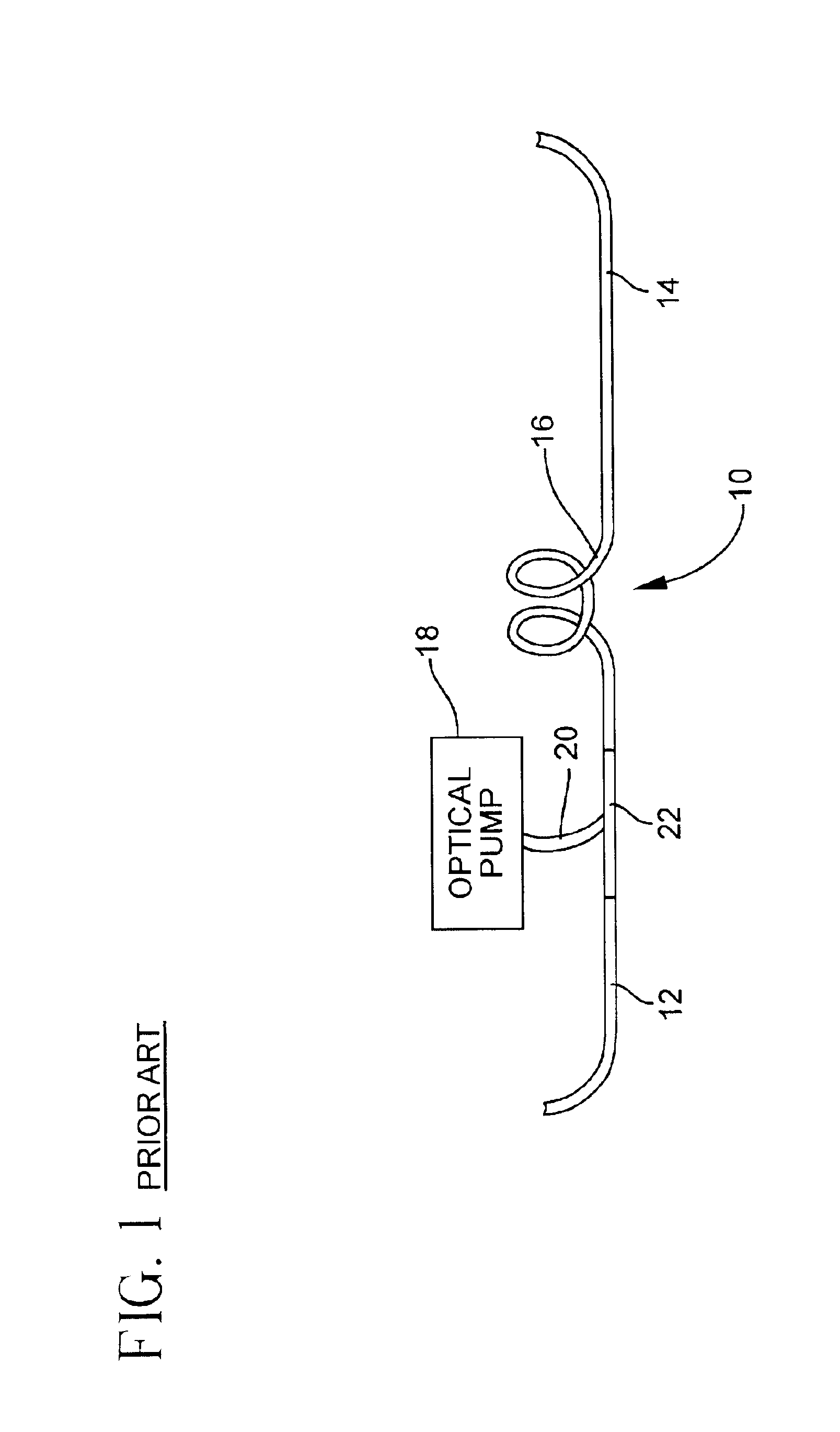
In the case of using the active fiber 30 as an amplifier 16 of FIG. 1, however, even a very small amount of signal reflection can cause undesirable multi-path interference effect.
However, other factors already discussed and to be seen, limit the optimum core size to the one corresponding to a nearly two-moded core.
Given the current material choice and capabilities of coupling optics, there is a limit to which the cladding size can be decreased before the pump coupling efficiency will start to suffer.
However, the index difference or delta between the core and the inner cladding cannot be made too small, or the optical field will simply not be confined in the core, as already discussed, and the core waveguide will have too much bend loss.
Unfortunately, the light emitting spot of a broad-area semiconductor laser is strongly asymmetric, with an aspect ratio of at least 100:1.

Method used


Image

  • Cladding-pumped 3-level fiber laser/amplifier
  • Cladding-pumped 3-level fiber laser/amplifier
  • Cladding-pumped 3-level fiber laser/amplifier

Examples


example 1

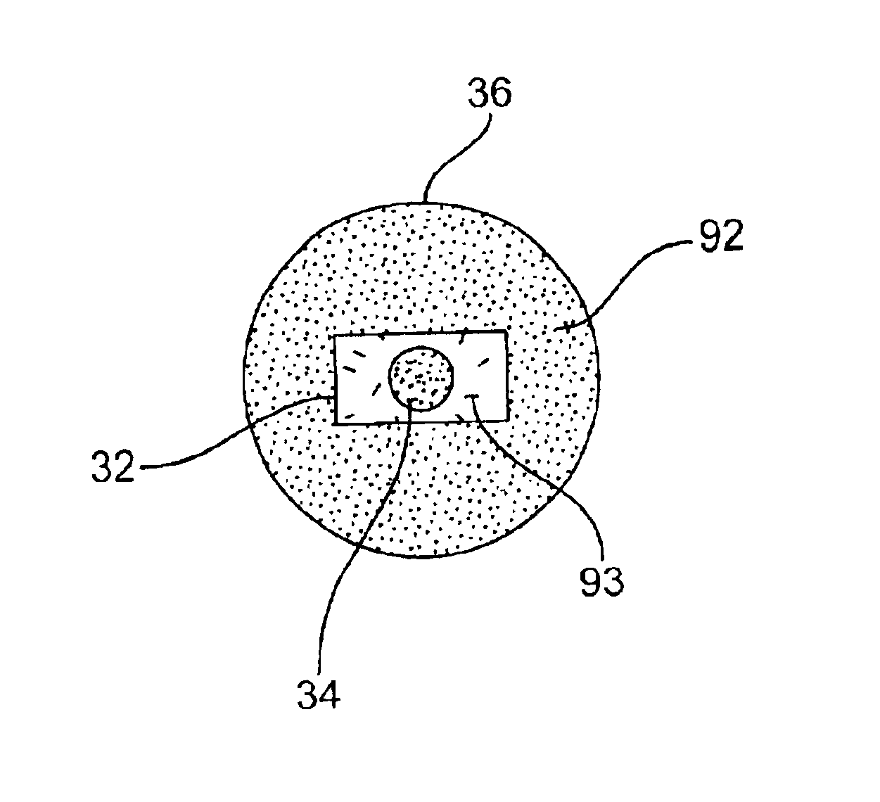
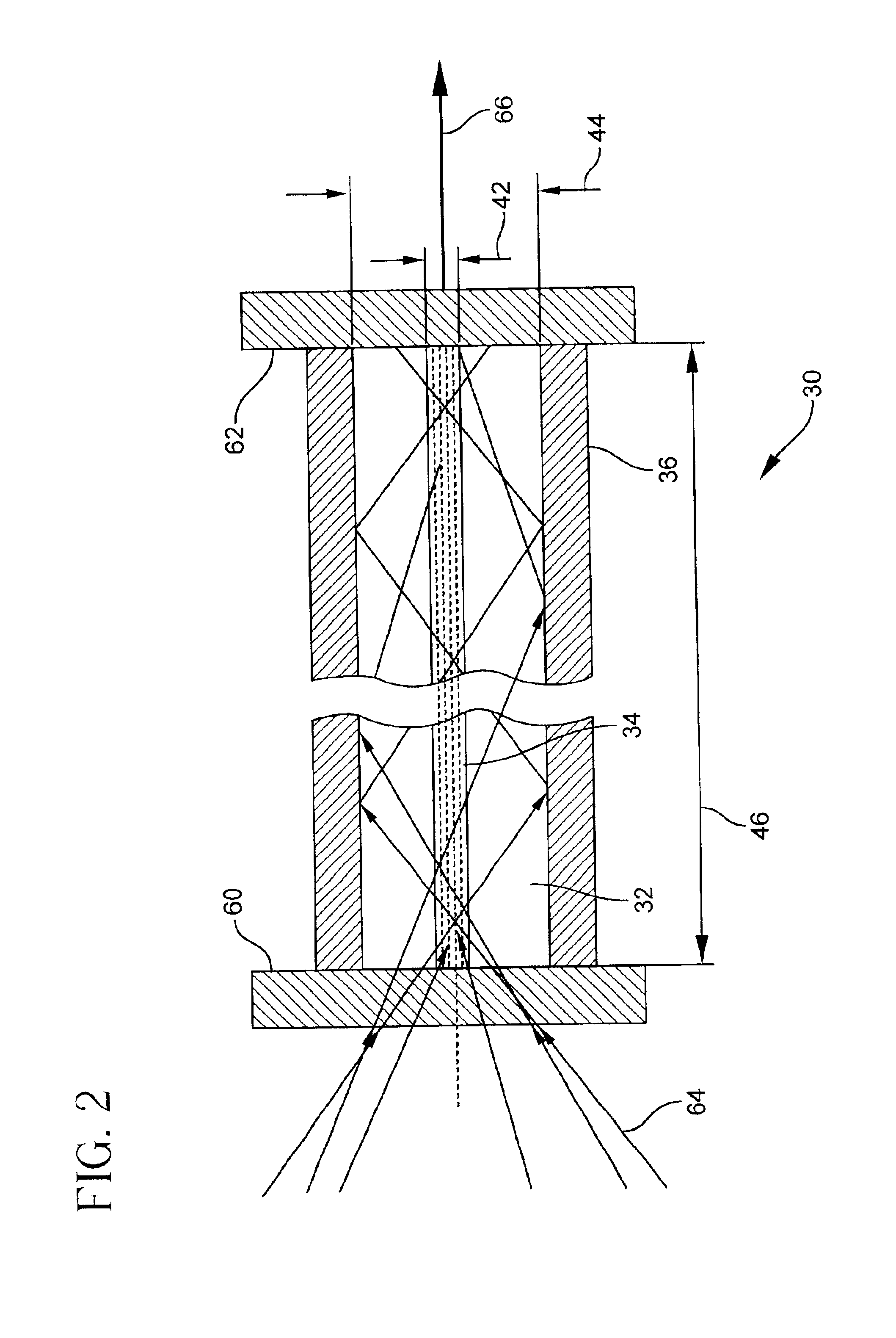
An efficient all-glass Yb-doped double-clad fiber laser 30 that delivers over 1 W of single-transverse-mode output at 978 nm when pumped with 2.5 W of launched power from a 200 .mu.m broad-area laser diode at 915 nm has an all-glass design. This double-clad fiber laser has a small clad-to-core ratio (CCR), combined with strong spectral and modal gain discrimination. The fiber core 34 and the first or inner cladding base glass 32 is a multi-component antimony-silicate. The step-index core 34 has a numerical aperture of 0.1 relative to the first cladding (NA.sub.core) The inner cladding 32, in turn has en effective numerical aperture of 0.5 (NA.sub.clad) relative to the boro-silicate glass second or outer cladding 36. The core 34 is uniformly doped with 0.45 wt % Yb having a fluorescence decay time of 875 .mu.s. The absorption and fluorescence spectra of the active fiber 30 produced using the triple-crucible method show that the quasi-four-level emission peaks at 1015 nm whereas the a...


PUM


Abstract

An optically active fiber (30) is disclosed for making a fiber laser (18) or an amplifier (16). This double-clad structured active fiber (30) has a core (34), doped with an optically excitable ion having a three-level transition. The core (34) has a core refractive index and a core cross-sectional area. An inner cladding (32) surrounds the core (34). The inner cladding (32) has an inner cladding refractive index less than the core refractive index, an inner cladding cross-sectional area between 2 and 25 times greater than that of the core cross-sectional area, and an aspect ratio greater than 1.5:1. An outer cladding (36) surrounds the inner cladding (32) and has an outer cladding refractive index less than the inner cladding refractive index.

Description

1. Field of the InventionThe present invention relates generally to active fibers for use as optical amplifiers and lasers for applications ranging from laser-machining and graphic arts to telecommunications, and in particular to 3-level double-clad fiber lasers and 3-level double-clad fiber amplifiers.2. Technical BackgroundOptical fiber is increasingly becoming the favored transmission medium for telecommunications due to its high capacity and immunity to electrical noise. Silica optical fiber is relatively inexpensive, and when fabricated as a single transverse mode fiber can transmit signals in the 1550 nm band for many kilometers without amplification or regeneration. However, a need still exists for optical amplification in many fiber networks, either because of the great transmission distances involved, or the optical signal being split into many paths.As illustrated schematically in FIG. 1, a conventional amplifier 10 is interposed between an input transmission fiber 12 and ...

Claims


Application Information

Patent Timeline
Patent Type & Authority Patents(United States)
IPC IPC(8): H01S3/06H01S3/067H01S3/094H01S5/20H01S3/0941H01S5/02H01S5/00H01S5/026H01S1/00
CPCH01S3/06716H01S3/0672H01S3/09415H01S3/094003H01S3/094019H01S3/06729
Inventor DEJNEKA, MATTHEW J.ELLISON, ADAM J.KUKSENKOV, DMITRI V.MINELLY, JOHN D.TRUESDALE, CARLTON M.ZENTENO, LUIS A.
Owner CORNING INC
Learn More