Eureka AIR delivers breakthrough ideas for toughest innovation challenges, trusted by R&D personnel around the world.

Micro and ultrafilters with controlled pore sizes and pore size distribution and methods for making

Inactive Publication Date: 2001-10-30
ELLIPSIS CORP
View PDF63 Cites 105 Cited by
  • Summary
  • Abstract
  • Description
  • Claims
  • Application Information

AI Technical Summary

Benefits of technology

An additional object of the present invention is to provide filter elements and a method for producing the same which have a high density of pores that exhibit short relatively linear flow paths.
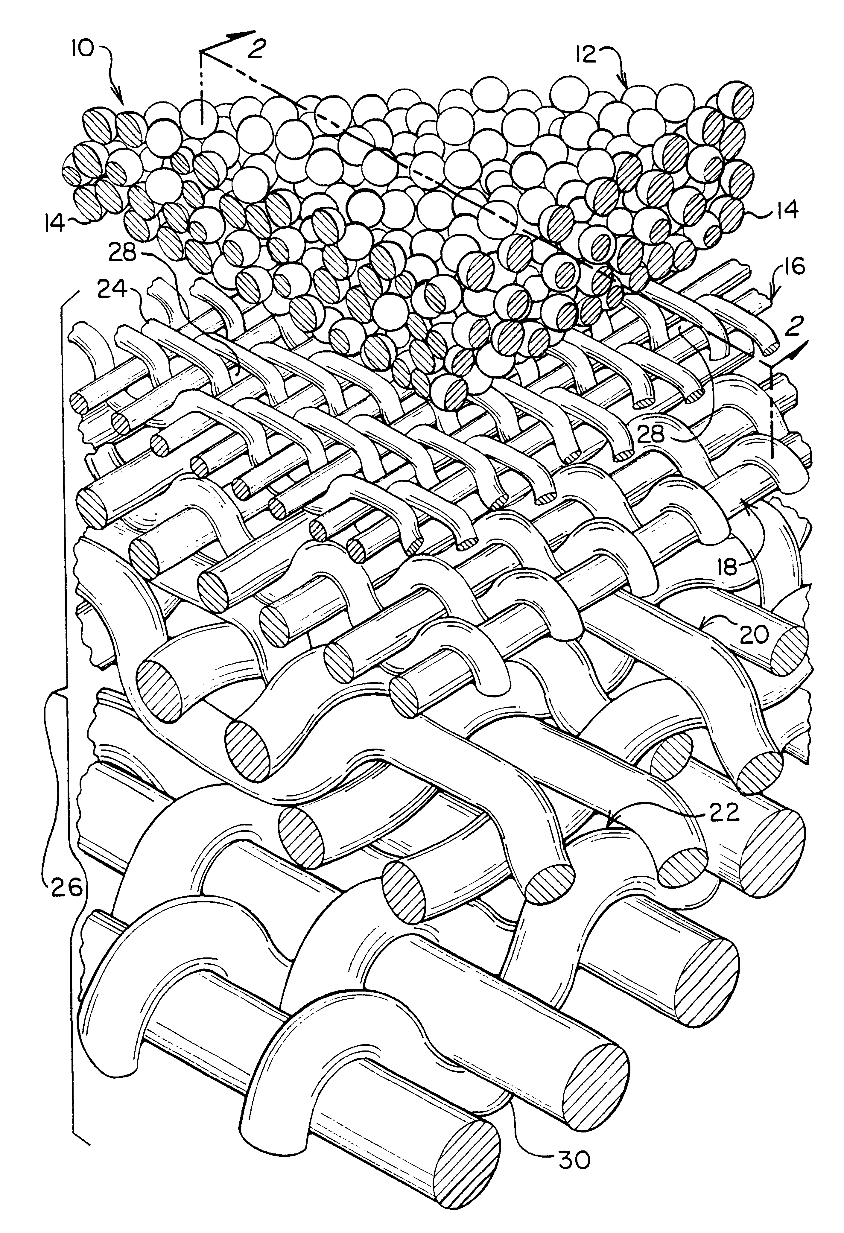
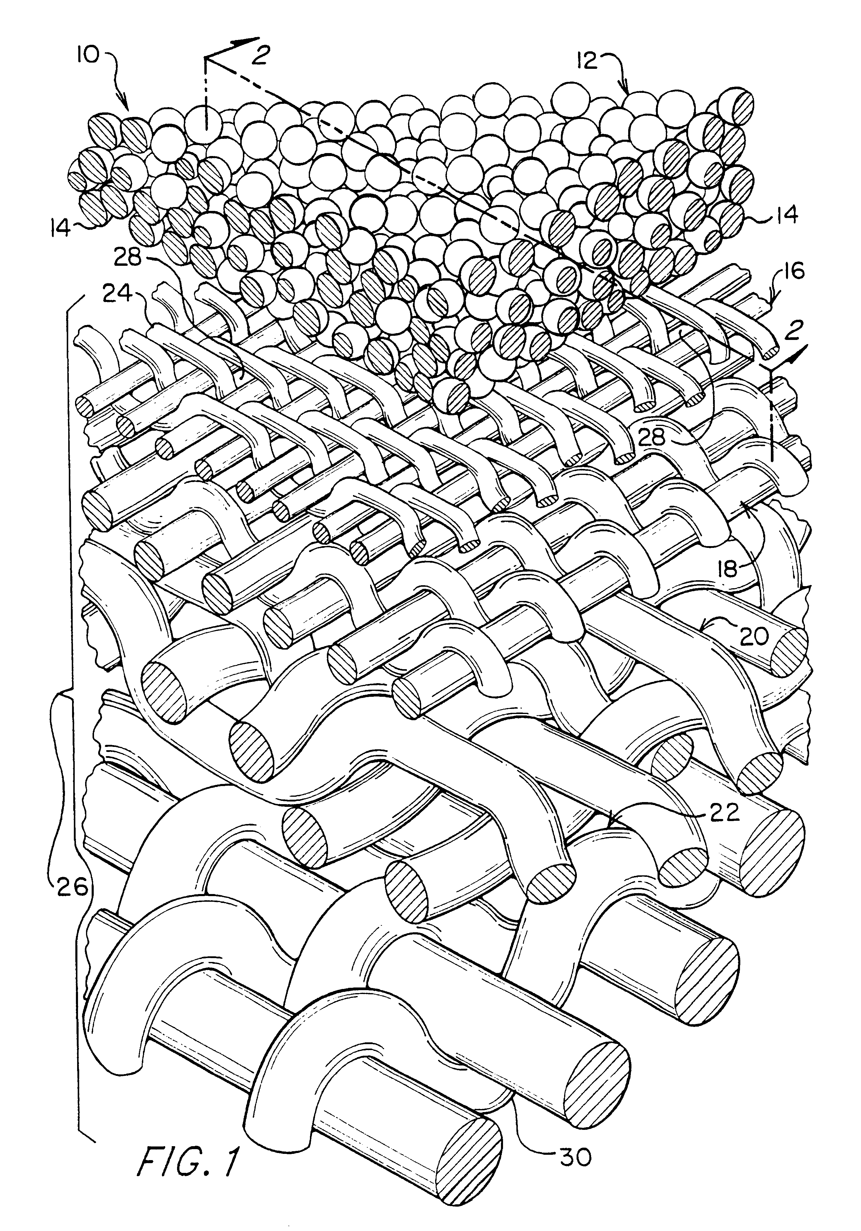
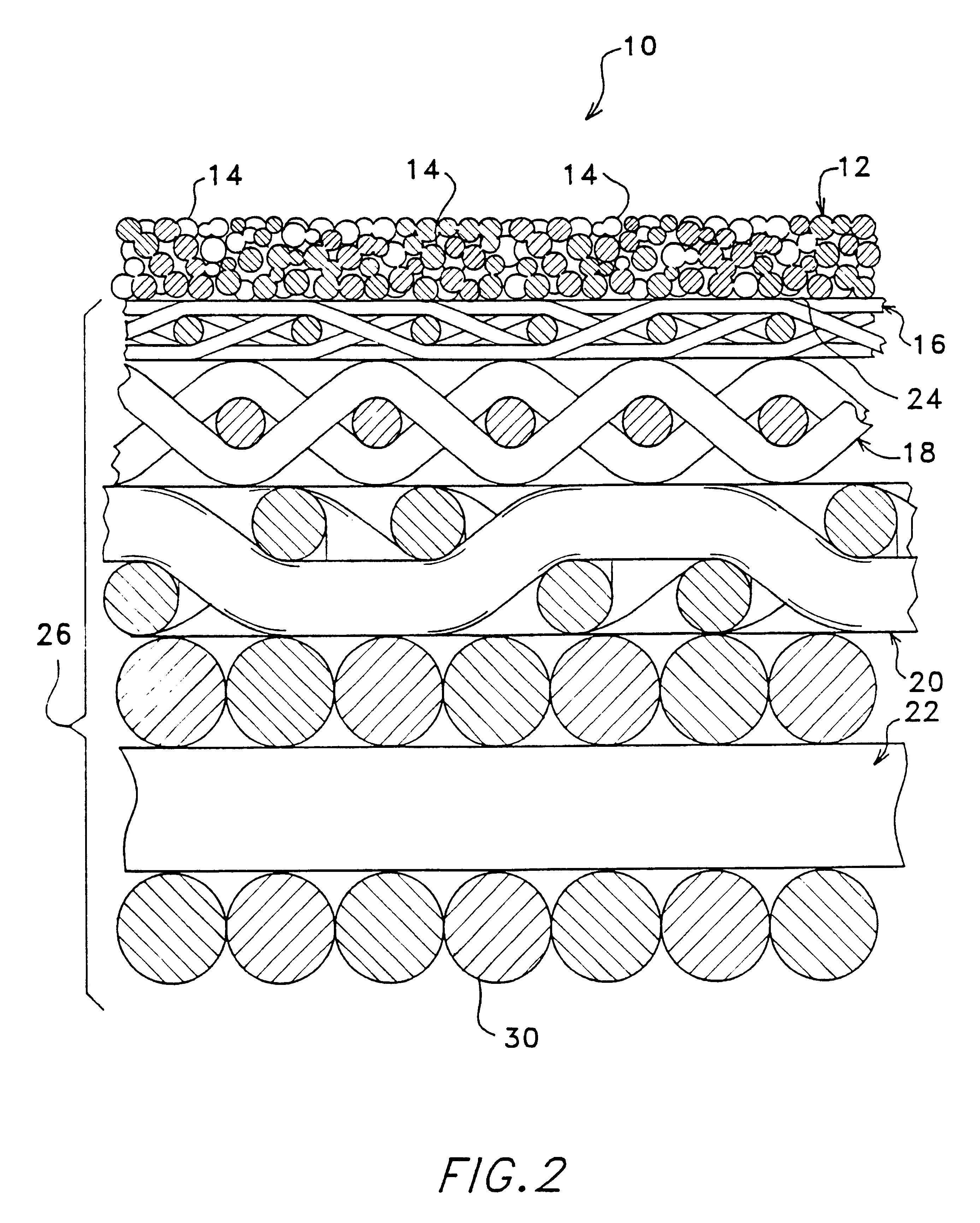
The filtering element 10, according to this invention, is represented in FIGS. 1 and 2, and essentially, comprises a membrane 12 comprised of contiguous particles 14 sintered to the surface 24 of a porous support 26. Prior to sintering, particles 14 having known maximum particle size diameter are mixed into a binder system to produce a suspension which is then deposited over the surface 24 of support 26 so that particles 14 are uniformly deposited thereon. Consequently, subsequent to sintering particles 14 are bound to one another and to surface 24 thereby forming membrane 12 having a consistently uniform pore size, pore size distribution and high permeability. Such a configuration not only allows high production rates with minimal pressure drop but also hinders plugging of pores 28, in the high-permeability support 26, with extraneous materials in the feed.
Support 26 serves as a base for the application of a suspension of dispersed particles 14 which ultimately form porous membrane 12, and thereby contributes to structural integrity, strength, and flexibility of be filtering device 10 according to the present invention. Wire mesh stainless steel screens are the preferred support: however, sintered metals, sintered ceramics sintered metal fiber meshes, sintered random metal fiber meshes, ceramic fiber meshes, electroformed screens, photoetched screens and plasma etched screens may also be used. Ideally, support 26 is a multi-structured design having four layers 16, 18, 20, and 22 of progressively coarser mesh sizes bonded together, using techniques such as fusion bonding or sintering in all overlapping manner. Layer 16 which provides supporting surface 24 for membrane 12 comprises the finest mesh count of the four layers. In the preferred embodiment of the present invention, layer 16 is a Dutch Twilled Weave (DTW) having a nominal mesh count of 325.times.2300 (the numbers refer to the number of wires per inch in each direction), and a 2 .mu.m nominal 8 .mu.m absolute pore size. Other fine meshes in the range of 510.times.3,600 to 165.times.1,400 may also be used. Layer 18, juxtaposed to layer 16, protects layer 16 from possible deformation under high pressure. Ideally the weave is a Single Plain Dutch Weave, although other types of weave including twill, double twill, reverse weave and so on can also be used. The mesh size of layer 18 is dependent on the mesh size of layer 16. Layer 20, the third layer, is positioned horizontally below layer 18 making the wire cloth laminate stable and improves the welding characteristics. As with layer 18, the mesh size of layer 20 will depend on the mesh size utilized in layer 18. The final layer 22, functions as a second support layer (layer 20 being the first) and is usually positioned or oriented 90 degrees to layer 20 for additional rigidity. Layer 22 is preferably a Reverse Plain Dutch Weave utilizing wires having a larger diameter. The mesh size of layer 22 is again dependent on the mesh size of layer 20. While substrate 26 may be fabricated by positioning layers 16, 18, 20, and 22 horizontally above one another and then bonding be individual layers together thereby forming a single element, substrate 26 is also commercially available from Purolator Products Company, Facet Filter Products Division, Greensboro, N.C. as a modified version of Purolater.TM..
The ceramic articles 211 used in this method of membrane 212 fabrication are not reduced to their metallic form under the processing conditions used. For example, alumina is not reduced to aluminum metal or even partially reduced under the processing conditions required to prevent the oxidation of metallic nickel or stainless steel. One additional advantage of having the ceramic particles 211 present is that the refractory ceramic particles 211 help inhibit the rotation and coalescence of the larger metallic particles 214 during sintering. This improves the uniformity of the pore size distribution of the metallic particle matrix. Furthermore specific dopants can be absorbed or adsorbed onto the surface of the ceramic particles 211 to increase filtration efficiency for the fluid(s) undergoing filtration and / or to effect specific chemical reactions over a very wide temperature range. Since little or no sintering of the ceramic particles 211 occurs during fabrication, the ceramic particles 211 are believed to be physically contained within the metallic matrix, however there may be some physical and / or chemical bonding occurring between the metallic and ceramic particles 214 and 211, respectively, ensuring membrane integrity especially since the coefficient of linear thermal expansion for the metallic and ceramic particles 214 and 211, respectively, may differ by a factor of between 2 and 10.

Problems solved by technology

While this type of filter has many desirable characteristics, it suffers from low efficiency, for the removal of fine particles due to relatively large pore sizes of the wire mesh structure In an effort to create filters having uniform pore sizes in the range of 10 micrometers to 0.01 micrometers or less, attempts, met with limited success, have been made to alter the underlying size of the pores in a porous substrate by the application of a second and possibly subsequent layer(s) of material.
The disadvantages associated with the techniques described above involve the plugging of the existing pores in the porous substrates by means of pressing powders into the openings and thereafter heating or annealing such powders to simply fill the pores to reduce their dimension.
Due to the loose attachment of the deposited material and the tortuous flow paths created these fillers cause a high pressure drop across the filter, since pressure drop through the filter is a function of pore size, number of pores, tortuosity of the flow path and length of the flow path.
Such attempts at cleaning the filters described above can destroy or remove significant portions of a weakly deposited membrane surface.
The deposition techniques disclosed by Gaddis, et al., Koehler and Trusov, et al., do not readily lend themselves to the construction of filter elements in a variety of geometric shapes.
Due to the flow characteristics of the deposited layers, non-uniformity of deposition can occur such that portions of the filter element will be completely closed while other portions of the filter element remain relatively open so that substantial inconsistency in filtering capabilities resides over the surface area of the filter element.

Method used


Image

  • Micro and ultrafilters with controlled pore sizes and pore size distribution and methods for making
  • Micro and ultrafilters with controlled pore sizes and pore size distribution and methods for making
  • Micro and ultrafilters with controlled pore sizes and pore size distribution and methods for making

Examples


example 2

Processing a Two Layer, "Graded", Membrane by Dip Coating

In addition to the 10 micron powder suspension formulated in Example 1 above. 316l, stainless steel powder with a particle size specification of minus 5 microns was formulated with the B73210 binder system and toluene in the ratio of 62 weight percent powder, 32 weight percent binder and 6 weight percent toluene. This mixture was ball milled for 6 hours in order to provide a homogenous suspension.

Substrate cleaning and masking was performed as described above in Example 1

A coating / film of the 10 micron suspension was deposited on the substrate using the dipping procedure described above in Example 1. This deposited film was allowed to dry for approximately 20 minutes at room temperature. After drying all additional film was deposited on the initial layer by dipping the substrate with the dried film into the 5 micron suspension. This dipping procedure was the same as previously described.

The second layer (5 micron suspension) w...

example 3

Processing a Membrane by Tape Casting

316L stainless steel powder with a particle size specification of minus 10 microns was formulated with the B73210 binder system in the ratio of 70 weight percent powder and 30 weight percent binder. This mixture was mixed through the use of a SPEX vibratory mill for 8 minutes in order to provide a homogenous suspension.

A "cast on glass" technique was used. Prior to casting, the glass was treated with a coating of lecithin to facilitate easy removal of the deposited "tape." Tape casting was performed using a hand held doctor blade to control the slurry thickness. The blade height was set at 0.01 in. This resulted in a green tape thickness on the order of 0.003 in. (75 .mu.m) after the elimination of volatile solvents. After drying, the green tape was removed Rom be glass casting surface and cut into one inch squares.

Substrates were modified 4-layer Purolator Poroplate laminate cut to 1.0 inch squares. The substrate cleaning procedures described in...

example 4

Processing a Membrane by Screen Printing

316L stainless steel powder with a particle size specification of minus 10 microns was formulated with ethyl cellulose and pine on to form the screen printing paste. Pine oil and ethyl cellulose were first formulated in a ratio of 9 to 1 respectively by weight. This "binder" was mixed by hand periodically over the time tame of 24 hours in order to ensure homogeneity. The 316L powder was then added to the binder in the ratio of 70% by weight. Mixing was once again performed by hand, periodically, over a 24 hour time period resulting in a "paste" suitable for printing.

Substrates were modified 4-layer Purolator Poroplate laminate out to 1.0 inch squares. The substrate cleaning procedures described above in Example 1 were followed.

A 0.75 in.sup.2 pattern was printed on the substrate using the 316L paste. After printing a layer, the substrate was heated to 100.degree.-150.degree. C. for several minutes on a hot plate in order to volatize the solven...


PUM

PropertyMeasurementUnit
Pore sizeaaaaaaaaaa
Percent by massaaaaaaaaaa

Abstract

A micro / ultrafiltering element (10) and method for making a filter element are provided. The filtering element comprises a multi-level support (26) having a filtering membrane layer (12) formed thereon comprising sintered particles (14) of uniform diameter. The filtering membrane preferably has an average pore size of from about 0.005-10 micrometers. The filter element is capable of being formed in a variety of geometrical shapes based on the shape of the porous support,

Description

The present invention relates to filtration technology and, more specifically to highly permeable micro- and ultrafilters having consistent uniform pore size and pore size distribution and methods for making them.Filtration systems play an important role in a wide variety of industrial and commercial processes which generally increase our quality of life. High efficiency filtration systems are currently being used in numerous medical applications, including but not limited to blood filtration and the separation of microorganisms such as, bacteria and viruses from biological or other fluids (both liquids and gases). In this regard, filtration technology is also beneficial in the drug, cosmetic and beverage industries. Filters are also used to a great extent in the semiconductor and microelectronics manufacturing industry for fine clarification and for the special cleaning of liquids and gases. In addition to their role in separating materials, micro- and ultrafilters may also be used...

Claims


Application Information

Patent Timeline
IPC IPC(8): B01D39/10B01D39/12B01D39/20B01D71/00B01D71/02B01J37/02B01J37/00B32B5/22B32B5/28
CPCB01D39/12B01D39/2034B01D39/2041B01D39/2082B01D67/0041B01D69/141B01D71/022B01J37/0215B32B5/28B01D2239/0442B01D2239/0471B01D2239/0478B01D2239/0654B01D2239/083B01D2239/10B01D2239/1216B01D2239/1241B01D2323/08B01D2325/04B01D2325/12B32B2305/80B32B15/02B32B15/16B32B2305/38B01D2323/081B01D71/02232B01D69/1411B01D71/02231B01D67/00411
Inventor HERRMANN, ROBERT C.LANDIN, STEVEN M.
Owner ELLIPSIS CORP
Why Eureka
Eureka Blog
Learn More