


Quick Research
Generate reliable direction feasibility study reports for your R&D in just a few steps.

Technical Q&A
Discover and master advanced knowledge NOW. Basics, ideas, possibilities, all at once.

Find Solutions
As an expert in R&D theories, this can generate solutions to your technical problems instantly.

Evaluate Feasibility
Analyze your overall solution with one click, know your potential R&D risks in advance.

Monitor Landscape
Get weekly tech updates, stay abreast of the latest tech innovations and key insights.
Thermal spray material, thermal spray coating and thermal spray coated article
a technology of thermal spray coating and thermal spray coating, which is applied in the direction of coatings, rare earth metal fluorides, chemistry apparatus and processes, etc., can solve the problems of circuit defects and possible erosion on the members, and achieve excellent plasma erosion resistance, excellent porosity, and excellent corrosion resistance.
- Summary
- Abstract
- Description
- Claims
- Application Information
AI Technical Summary
Benefits of technology
Problems solved by technology
Method used
Image

Examples
examples
[0066]Several Examples related to the present invention are described below, but the present invention is not to be limited to these Examples.
embodiment 1
[0067]As Thermal Spray Material No. 1, was obtained an yttrium oxide powder generally used as a protective coating on members in semiconductor device manufacturing equipment. As Thermal Spray Material No. 2, was obtained an yttrium fluoride powder being a rare earth element halide. An yttrium-containing compound and a fluorine-containing compound were suitably mixed and calcined to obtain Thermal Spray Materials Nos. 3 to 8 in powder forms. These thermal spray materials were tested for physical properties. The results are shown in Table 1. In Table 1, for reference, among the thermal spray materials disclosed in Patent Document 1, the data of thermal spray materials (Examples 10 and 11 in Patent Document 1) with relatively high YOF contents are also shown together as Comparative Examples A and B.
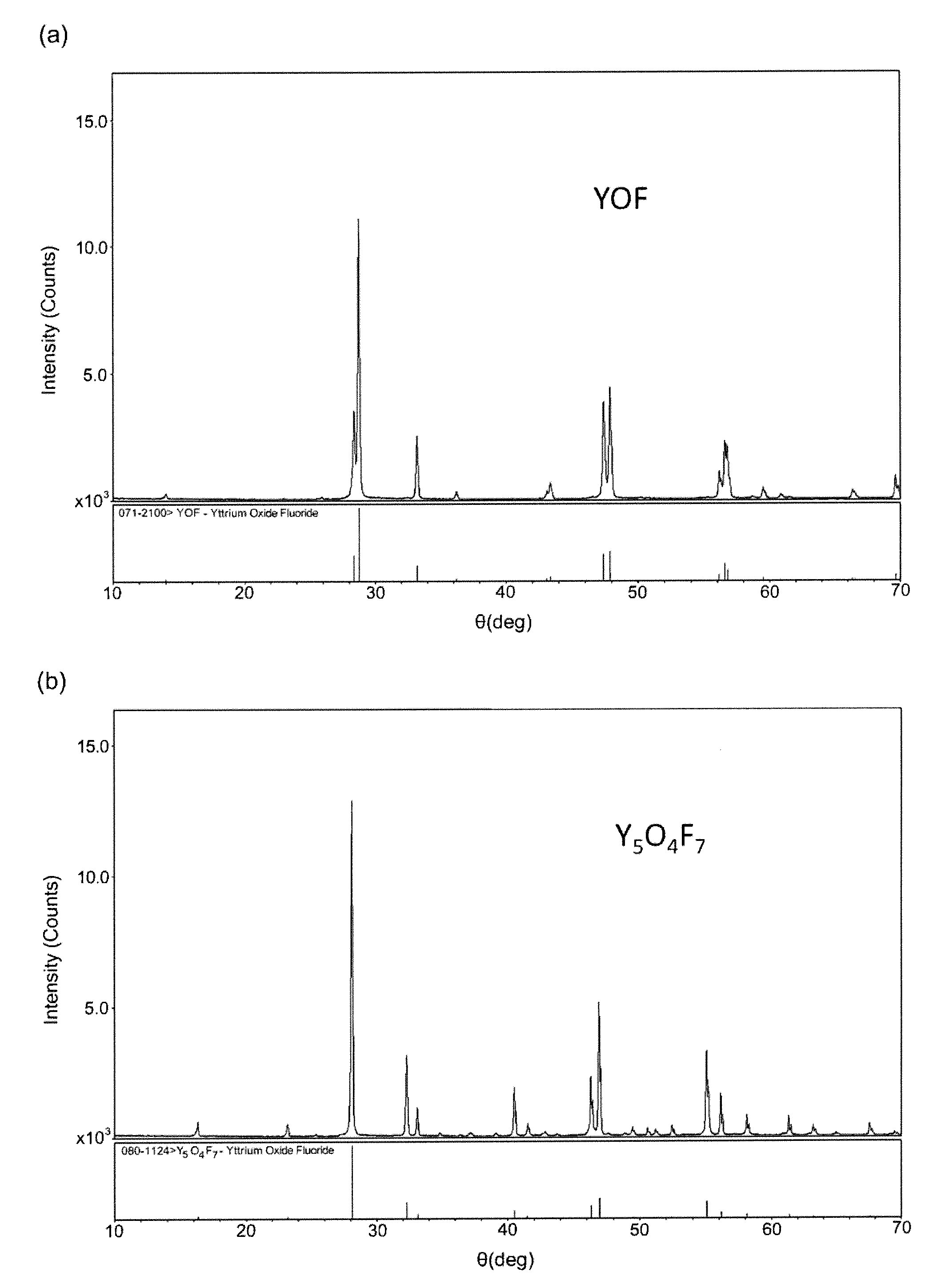
TABLE 1XRD-detectedphases ofRelative intensities of XRD main peaksIntensitythermal sprayY—O—F speciesratioOxygenNo.materialY2O3YF3YOFY7O6F9Y6O5F8Y5O4F7(IB + IC) / IA(wt %)1Y2O310000000—21.32YF...
embodiment 2
[0077]By plasma thermal spraying of Thermal Spray Materials Nos. 1 to 8, thermal sprayed articles were fabricated, comprising thermal spray coatings of Nos. 1 to 8. The thermal spray was carried out under the conditions below.
[0078]In particular, as the substrate, a 70 mm by 50 mm by 2.3 mm plate of an aluminum alloy (A16061) was obtained, blasted with a brown alumina abrasive (A#40) and used. The plasma thermal spray was carried out, using a commercial plasma spray gun (SG-100 available from Praxair Surface Technologies). Using argon gas at 50 psi (0.34 MPa) and helium gas at 50 psi (0.34 MPa) as the plasma gas, plasma was generated at 37.0 V voltage and 900 A current. The thermal spray materials were supplied with a powder feeder (Model 1264 available from Praxair Surface Technologies) to the thermal spray device at a rate of 20 g / min to form 200 μm thick thermal spray coatings. The feed rate of the spray gun was set to 24 m / min and spray distance to 90 mm.
[0079]The resulting ther...
PUM
| Property | Measurement | Unit |
|---|---|---|
| Fraction | aaaaa | aaaaa |
| Fraction | aaaaa | aaaaa |
| Fraction | aaaaa | aaaaa |
Abstract
Description
Claims
Application Information
 - R&D Engineer
- R&D Manager
- IP Professional
- Industry Leading Data Capabilities
- Powerful AI technology
- Patent DNA Extraction
Browse by: Latest US Patents, China's latest patents, Technical Efficacy Thesaurus, Application Domain, Technology Topic, Popular Technical Reports.
© 2024 PatSnap. All rights reserved.Legal|Privacy policy|Modern Slavery Act Transparency Statement|Sitemap|About US| Contact US: help@patsnap.com