
Stator assembly structure for axial flux electric machine

a technology of axial flux electric machines and assembly structures, which is applied in the direction of mechanical energy handling, magnetic circuits characterised by magnetic materials, and magnetic circuit shapes/forms/construction, etc., can solve the problems of heat dissipation of copper loss of coils, power loss may still be produced, and the effect of reducing implementation costs and easy generation of concave grooves

Active Publication Date: 2013-06-06
IND TECH RES INST
View PDF5 Cites 19 Cited by
  • Summary
  • Abstract
  • Description
  • Claims
  • Application Information

AI Technical Summary

Benefits of technology

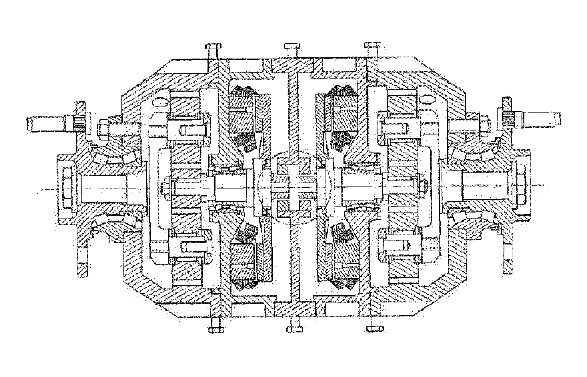
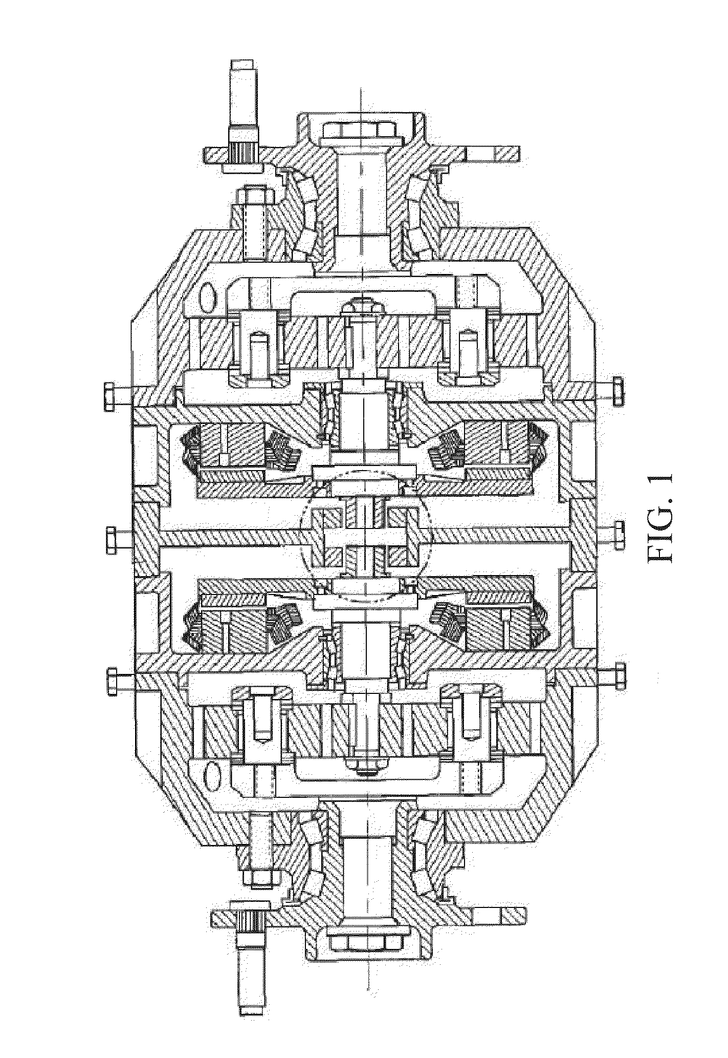
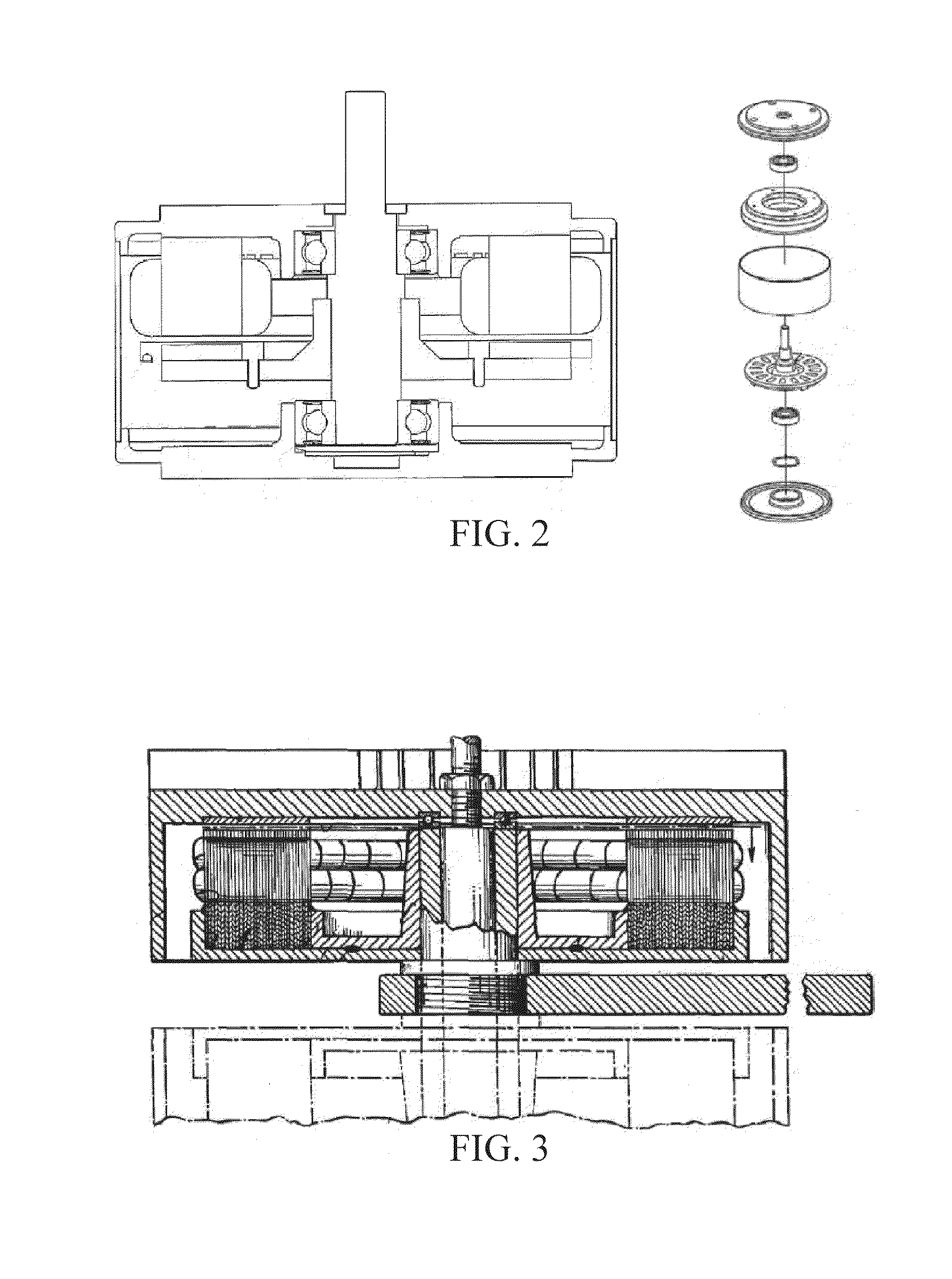
The present invention provides a stator assembly structure for an axial flux electric machine that allows the stator and the disk-type stator seat to be integrated together by casting or mold forming, without the need for precise and expensive processing and special assembly process. The stator structure includes a junction surface with a tooth-like structure that allows the stator and the disk-type stator seat to bear a larger rotation stress. The stator structure also has a good heat dissipation characteristic. The present invention also fixes the problem of the stator enduring a larger axial suction of the rotator magnet by providing a method to stack multiple layers of thin silicon steel in the stator assembly.

Problems solved by technology

The tiny electric impedance may still produce power loss (i.e. copper loss) under the function of large current, and the copper loss of the coil may be dissipated in the form of heat.
If the heat cannot be rapidly transmitted to the outside, the heat is accumulated to cause the increasing of the temperature of the coil and burn-out of the electric insulating coating of the coil.
The eddy current may generate the power loss in the ferrous material with a relatively high electric impedance (i.e. ferrous loss).
If the heat generated by the copper loss and the ferrous loss cannot be rapidly transmitted to the outside, the temperature accumulated on the coil becomes higher, which may generate a heat shock on the enameled wire of the coil.
The high temperature may accelerate the aging and deterioration of the electric insulating coating between the wires of the coil.
), the electric insulating coating is punched, thus causing the short circuit burn-out and failure of the coil.
Since the thermal energy needs to flow through the junction surface between the stator and the disk-type stator seat, if the structure between the stator and the disk-type stator seat does not generate a sufficient contact surface area, the coefficient of thermal conductivity of the junction surface is quite low (i.e. the thermal impedance is very large) so the heat is hard to pass.
That is to say, the heat of the copper loss of the coil and the ferrous loss of the stator is difficult to flow to the disk-type stator seat.
Even if the disk-type stator seat has a good heat dissipation capability, the entire stator assembly still cannot endure the high power working as the temperature is extremely high.
Since the stator structure is mostly formed by a plurality of very thin silicon steels stacked together, the stator made of multiple layers of silicon steel material is difficult to be processed by mechanical cutting.
Not only the cost is very high, but also the required precision tolerance size and surface roughness cannot be achieved by the contact surface.
If the grinding manner is adopted to process and improve the size precision, the cost is higher than the mechanical cutting method, so the grinding method does not meet the economic benefit requirement.
Therefore, the major concerns in the prior art include: generating the effective junction surface area between the stator and the disk-type stator seat and not achieving a high proportion of total contact between the two physical bodies.
As the adhesive with high adhesion, high thermal conductivity and high thermal resistance has not been developed, the contact surface area between the stator and the disk-type stator seat is still not large enough.
When the conventional method is applied in the high-power electric machine, due to the poor thermal conductivity, the temperature of the coil is too high, thus causing the limitation to the application power, and an axial flux disk electric machine of high-power density cannot be further developed, which is the biggest deficiency in the prior art.
The stator has the conventional nut holes for fixing the stator on the motor casing with screws, so the heat dissipation between the stator and the stator seat is still unsatisfactory. FIG. 3 has not disclosed the technique of forming convex or concave tooth-like structures on the stator junction surface to enhance the binding force.
The stator is fixed on the motor stator seat casing by a conventional welding method, so the heat dissipation between the stator and the stator seat is still unsatisfactory and needs modification.
There are technical difficulties in realizing the good contact state of the junction surface between the stator and the disk-type stator seat, and the best solution is one-piece casting or mold forming of the both.
There are also difficulties in casting the stator and the disk-type stator seat together.

Method used


Image

  • Stator assembly structure for axial flux electric machine
  • Stator assembly structure for axial flux electric machine
  • Stator assembly structure for axial flux electric machine

Examples


third embodiment

[0051]FIG. 7 is a schematic view of a stator structure according to the present invention. Referring to FIG. 7, in mass production, if the annular silicon steel pie is fabricated by punching, the silicon steels with the ascending sizes are stacked to form the pie stator components 15 with the identical single or multiple coil accommodation slots 12 and the tenon 14 and the engaging slot 13. Then, the pie stator components 15 are connected by a plurality of sectional pie fixing members 16 in the annular direction into the annular stator to form a complete-circle-shaped silicon steel. Each stator component 15 is buckled with the tenon 14 and the engaging slot 13 to avoid disengagement. The complete-circle-shaped silicon steels formed by the stator components 15 engaged together are stacked to form a barrel stator 1 in a manner of plane matching. The barrel stator 1 has a central line 10 and the pie may also be fabricated by a powder metallurgy process with a soft magnetic material. Th...

fourth embodiment

[0052]FIG. 8 is a schematic view of a stator structure according to the present invention. Referring to FIG. 8, the fixing member 16 of the present invention may also be welded on the junction surface of the stator 1 and the stator seat by the steel sheet or round bar with a smaller size. The stacked pie silicon steel is welded on the steel sheet or round bar one by one without getting scattered, and the steel sheet is drilled with the round holes to enhance the combination force of engaging the stator 1 and the stator seat (not shown) and avoid getting loose. Or, the fixing member 16 may be a column, which is firstly fixed in the round hole of the stator and is fixed with the stator and the column to one piece during the fused-casting of the stator seat.

[0053]FIG. 9 is a schematic view of a combination of the stator and the stator seat with water cooling heat dissipation according to an embodiment of the present invention. Referring to FIG. 9, the stator 1, the cooling water pipe 8...


PUM


Abstract

A stator assembly structure for an axial flux electric machine is designed. The back iron for each silicon steel disk stator is formed into a specific structure with tooth-like protrusions for allowing the same to be integrated with the disk-type stator seat, while the disk-type stator seat is made of a material suitable for casting or mold forming. A coil is mounted on the disk stator, and a stator assembly is achieved by integrating the stator, the coil and the stator seat. The stator and the disk-type stator seat of the stator assembly are manufactured by using a one-piece cast or one-piece mold forming method so as to enable the contact surfaces of the stator and the stator seat to engage with each other even more tightly, and consequently enable the heat generated from the coil to be transmitted rapidly from the disk stator to the disk-type stator seat.

Description

BACKGROUND[0001]1. Field[0002]The present invention relates to a stator assembly structure for an axial flux electric machine, and more particularly, to an architecture of a junction surface of the stator and the disk-type stator seat formed with at least one tooth-like engagement structure; the stator manufactured by cutting or punching a silicon steel easily produces concave grooves or convex teeth on the axial surface of the stator; no matter whether the disk-type stator seat is made of a metal material such as Al or Mg by casting or a non-metallic material with good thermal conductivity such as an engineering plastic by mold forming, the stator of the present invention has the junction surface with the tooth-like structure like a groove channel that allows the liquid disk-type stator seat material to flow easily so as to enable the stator and the disk-type stator seat made of different materials to be integrated more easily by casting or mold forming, and the tooth-like structur...

Claims


Application Information

Patent Timeline
Patent Type & Authority Applications(United States)
IPC IPC(8): H02K1/18H02K9/19
CPCH02K21/24H02K1/02H02K1/14H02K1/182H02K1/20H02K15/00H02K9/19H02K9/22H02K15/022H02K16/00H02K7/006H02K9/227H02K5/203
Inventor WEI, TSENG-TEHUANG, SHIAN-HSUANGU, HUAN-LUNGLO, SHIH-MINGCHENG, LI-JU
Owner IND TECH RES INST
Learn More