
Substrate comprising aluminum/graphite composite, heat dissipation part comprising same, and LED luminescent member

a technology of led luminescent member and heat dissipation part, which is applied in the direction of solid-state devices, metal-working apparatuses, synthetic resin layered products, etc., can solve the problems of led devices being destroyed, material cost, and warping, so as to reduce material loss, heat dissipation properties and reliability, and efficient production

Active Publication Date: 2011-12-29
DENKA CO LTD
View PDF4 Cites 17 Cited by
  • Summary
  • Abstract
  • Description
  • Claims
  • Application Information

AI Technical Summary

Benefits of technology

[0013]Aluminum-graphite composites excelling in properties such as thermal conductivity can be suitably produced by squeeze casting. However, due to the high cost of the materials used in squeeze casting, the LED light emitting elements can become expensive when using aluminum-graphite composites produced normally by squeeze casting as the substrates in LED light emitting elements.
[0016]The present inventors performed diligent research toward achieving the above-described purpose, as a result of which they discovered that an aluminum-graphite composite excelling in thermal conductivity, thermal expansion and strength properties can be efficiently produced by squeeze casting an isotropic graphite material in the form of a rectangular parallelepiped to form a composite with an aluminum alloy, and a substrate consisting of a plate-shaped aluminum-graphite composite can be efficiently obtained by reducing material losses due to the cutting reserve (cutting width) by appropriately adjusting the processing conditions with a multi-wire saw. Furthermore, they discovered that an LED light emitting element excelling in heat dissipation properties and reliability can be obtained by appropriately changing the substrate shape, insulation material and circuit arrangement, thereby completing the present invention. For the purposes of the present specification, “substrate” shall refer to the substrate before attachment of copper foil and electronic components.

Problems solved by technology

However, coke-type graphite materials are strongly anisotropic, so aluminum-graphite composites obtained by forming composites with aluminum also have anisotropic properties.
When using extremely anisotropic materials, warping can occur, and in the worst case, the LED devices can be destroyed.
However, due to the high cost of the materials used in squeeze casting, the LED light emitting elements can become expensive when using aluminum-graphite composites produced normally by squeeze casting as the substrates in LED light emitting elements.

Method used

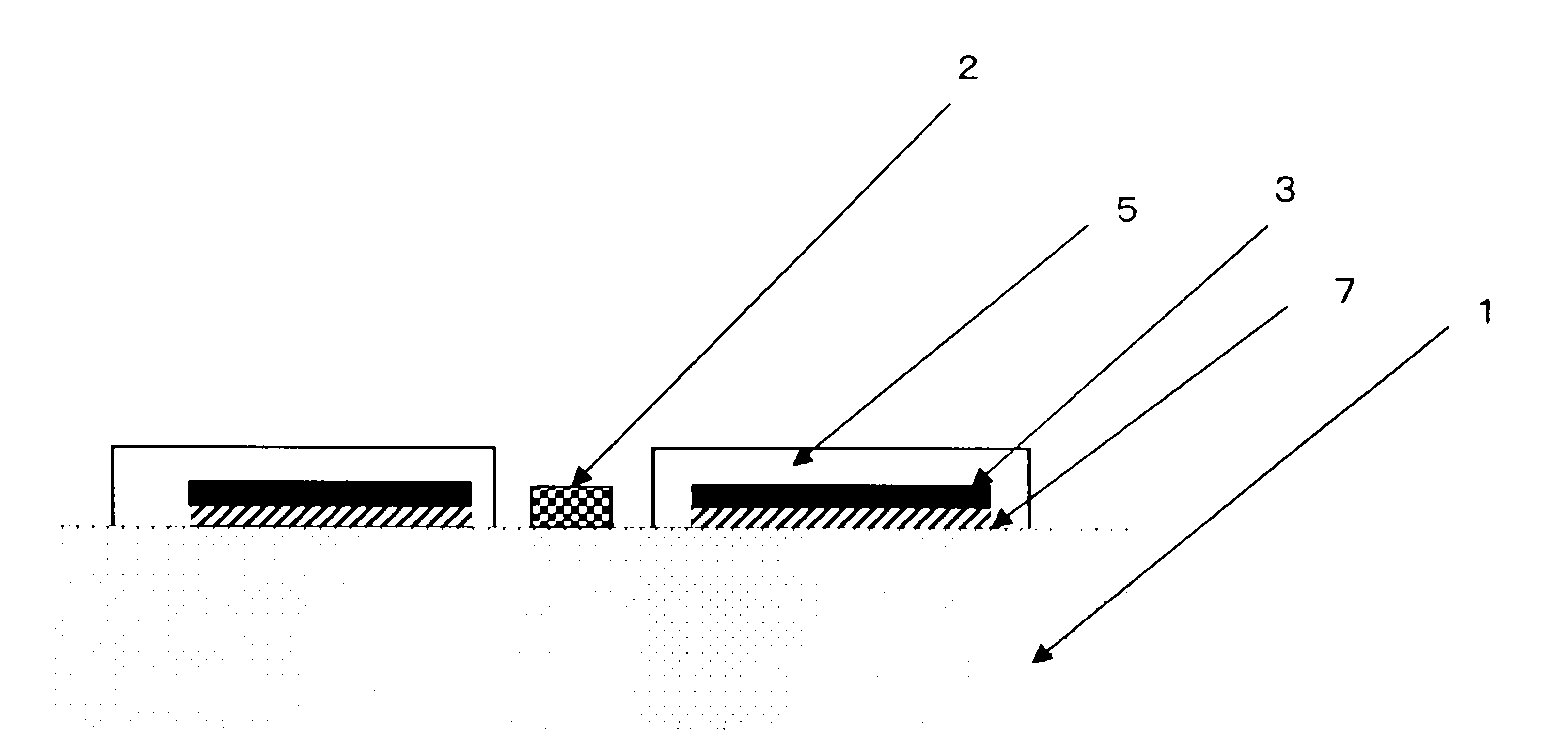
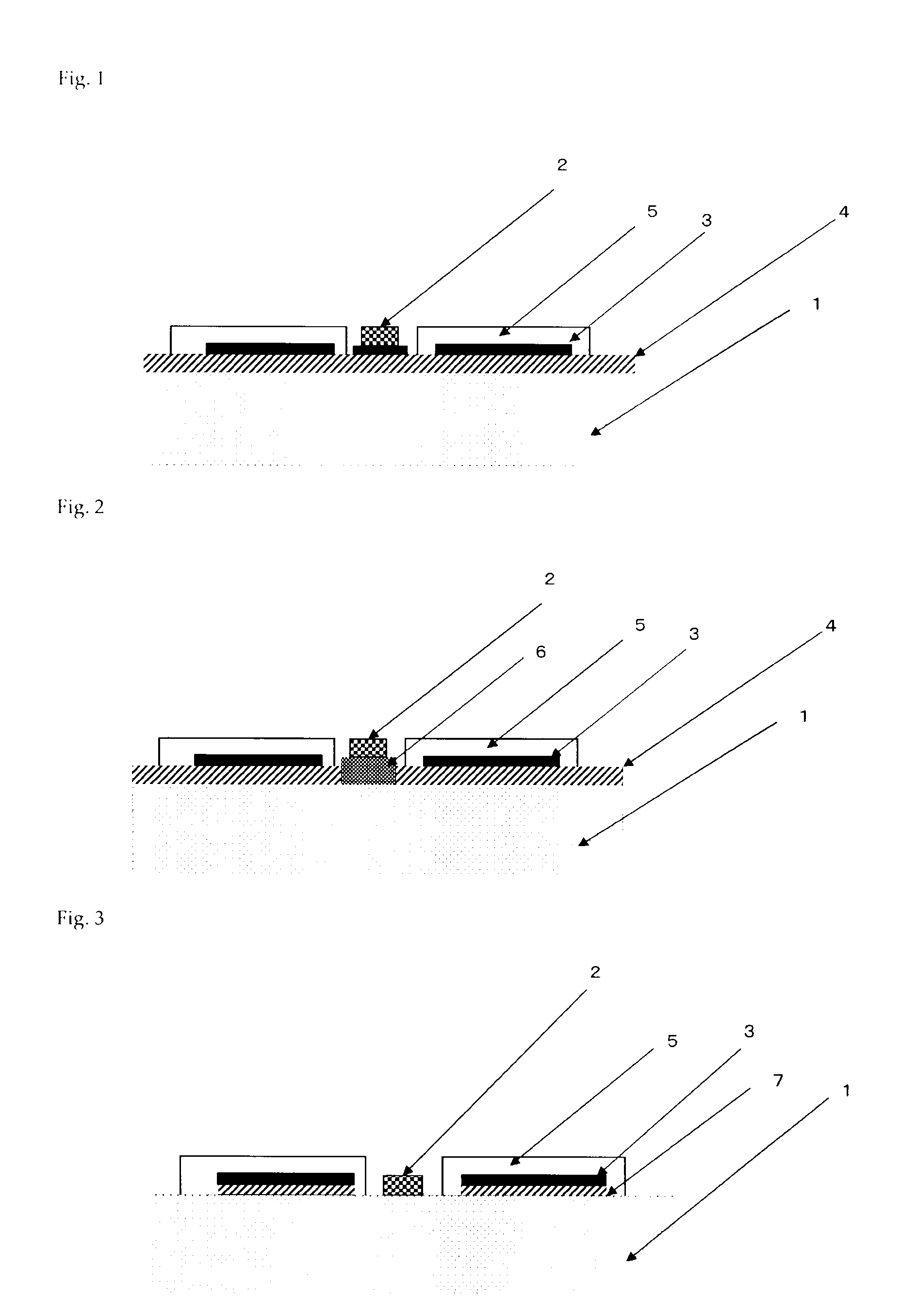

Image

  • Substrate comprising aluminum/graphite composite, heat dissipation part comprising same, and LED luminescent member
  • Substrate comprising aluminum/graphite composite, heat dissipation part comprising same, and LED luminescent member

Examples


examples 1 and 2

[0077]As Example 1, an isotropic graphite material (Tokai Carbon 6347) of bulk density 1.83 g / cm3, and as Example 2, an isotropic graphite material (Tokai Carbon G458) of bulk density 1.89 g / cm3, were worked to the shape of a rectangular parallelepiped of dimensions 200 mm×200 mm×250 mm, then sandwiched between iron plates of thickness 12 mm coated with a graphite mold release agent, and coupled with M10 nuts and bolts to form a stack. The resulting stack was preheated for 1 hour in an electric furnace with a nitrogen atmosphere at a temperature of 650° C., then placed in a preheated press mold of inner diameter 400 mm×height 300 mm, an aluminum alloy melt containing 12 mass % of silicon was poured in, and a pressure of 100 MPa was applied for 20 minutes to infiltrate the isotropic graphite material with the aluminum alloy. Next, after cooling to room temperature, the aluminum alloy and iron plate portions were cut with a wet band-type saw, resulting in a 200 mm×200 mm×250 mm alumin...

example 3

Led Light Emitting Element Production Example

[0082](1) The plate-shaped aluminum-graphite composite of Example 1 was electroplated to form a copper layer 35 μm thick on one entire surface of the composite, then the copper layer other than at the desired portions was removed by etching to form an aluminum-graphite composite having copper bumps. On the other hand, 100 parts by mass of bisphenol F-type epoxy resin (Epicoat 807, epoxy equivalent=173, Yuka Shell Epoxy) as an epoxy resin, 5 parts by mass of the silane coupler γ-glycidoxypropylmethyl diethoxysilane (AZ-6165, Nippon Unicar) and 500 parts by mass of alumina of average grain size 5 μm (AS-50, Showa Denko) as an inorganic filler were mixed together in a general-purpose mixer / stirrer, and as a curing agent, 45 parts by mass of polyoxypropylene amine (Jeffamine D-400, Texaco Chemicals) was added and mixed. This as applied to the 35 μm-thick copper foil to a thickness of 100 μm and put into the B-stage state to prepare a copper f...

example 4

Led Light Emitting Element Production Example

[0083]The plate-shaped aluminum-graphite composite obtained in Example 1, a bonding material consisting of an alloy composed of 95% Al-4% Cu-1% Mg and having a thickness of 0.3 mm, and a 0.4 mm thick Al circuit were stacked in that order to form a single set, and ten sets were stacked with spacers placed in between. These were heated for ten minutes at 610° C. in a vacuum (batch furnace) of 4×10⁻³ Pa while applying pressure at 500 MPa in the direction perpendicular to the substrate surface consisting of an aluminum-graphite composite from outside the furnace using a hydraulic uniaxial press device via a carbon push rod, thereby bonding them together, to form an aluminum-graphite composite circuit board. Next, a white solder resist (PSR4000-LEW1, Taiyo Ink) was applied via a screen onto a specific circuit, then UV-cured. Furthermore, an insulated LED chip (1 mm2) was adhered over the electrolytic copper foil exposed portion by an Ag paste,...


PUM

PropertyMeasurementUnit
thicknessaaaaaaaaaa
temperatureaaaaaaaaaa

Abstract

A process for producing a substrate, which comprises processing an aluminum / graphite composite into plates having a thickness of 0.5-3 mm using a multi-wire saw under the following conditions (1) to (4): (1) the wires have abrasive grains bonded thereto which are one or more substances selected from diamond, C—BN, silicon carbide, and alumina and have an average particle diameter of 10-100 μm; (2) the wires have a diameter of 0.1-0.3 mm; (3) the wires are run at a rate of 100-700 m / min; and (4) the composite is cut at a rate of 0.1-2 mm / min. The aluminum / graphite composite has a surface roughness (Ra) of 0.1-3 μm, a thermal conductivity at 25° C. of 150-300 W / mK, a ratio of the maximum to the minimum value of thermal conductivity in three perpendicular directions of 1-1.3, a coefficient of thermal expansion at 25-150° C. of 4×10⁶ to 7.5×10⁻⁶ / K, a ratio of the maximum to the minimum value of coefficient of thermal expansion in three perpendicular directions of 1-1.3, and a three-point bending strength of 50-150 MPa.

Description

TECHNICAL FIELD[0001]The present invention relates to a substrate composed of an aluminum-graphite composite, a heat dissipating component using same, and an LED light-emitting member.BACKGROUND ART[0002]In recent years, there has been much interest in light-emitting diodes (hereinafter referred to as LEDs) as illumination and light generating means capable of being made lightweight, thin and with low power consumption. LED devices are devices that emit light when a forward current is passed through the pn junction of a semiconductor, produced using III-V semiconductor crystals such as GaAs and GaN. Progress in techniques of semiconductor epitaxial growth and light-emitting device processing has resulted in development of LEDs of exceptional conversion efficiency, that are widely used in various fields.[0003]LED devices are composed of a p-type layer and an n-type layer formed by epitaxial growth of III-V semiconductor crystals on a monocrystalline growth substrate, and an optically...

Claims


Application Information

Patent Timeline
Patent Type & Authority Applications(United States)
IPC IPC(8): H01L33/64B32B3/00B32B3/10B26D1/553B32B15/00
CPCC04B41/009Y10T428/24273C04B41/88C04B2111/00844H01L23/142H01L23/373H01L23/3735H01L33/641H05K1/05H05K2201/0323C04B41/5155Y10T428/24917Y10T428/24909H01L2924/0002B22F3/26C04B41/4519C04B41/4521C04B41/4523C04B41/5096C04B35/522C04B38/00H01L2924/00B23D61/185B23D57/0023B28D5/045Y10T83/04
Inventor HIROTSURU, HIDEKIHIGUMA, SATOSHINARITA, SHINYATSUJIMURA, YOSHIHIKO
Owner DENKA CO LTD
Learn More