
Conductive substance-adsorbing resin film, method for producing conductive substance-adsorbing resin film, metal layer-coated resin film using the same, and method for producing metal layer-coated resin film

a technology of conductive substance and resin film, which is applied in the direction of other chemical processes, liquid/solution decomposition chemical coating, coating, etc., can solve the problems of inability to form fine wirings, inability to achieve sufficient adhesion between metal layer and insulating resin film, and complex operation, etc., to achieve excellent adhesion and less unevenness

Active Publication Date: 2010-05-06
FUJIFILM CORP
View PDF1 Cites 40 Cited by
  • Summary
  • Abstract
  • Description
  • Claims
  • Application Information

AI Technical Summary

Benefits of technology

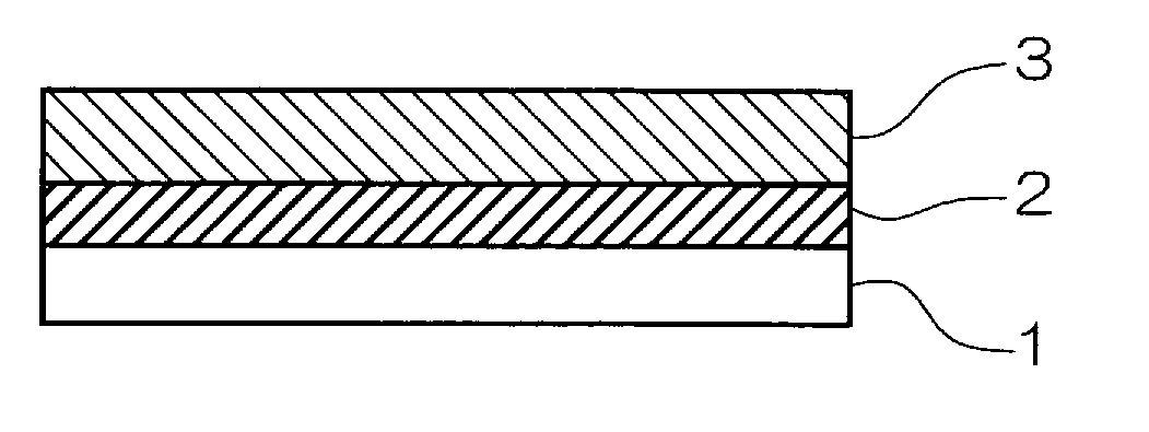
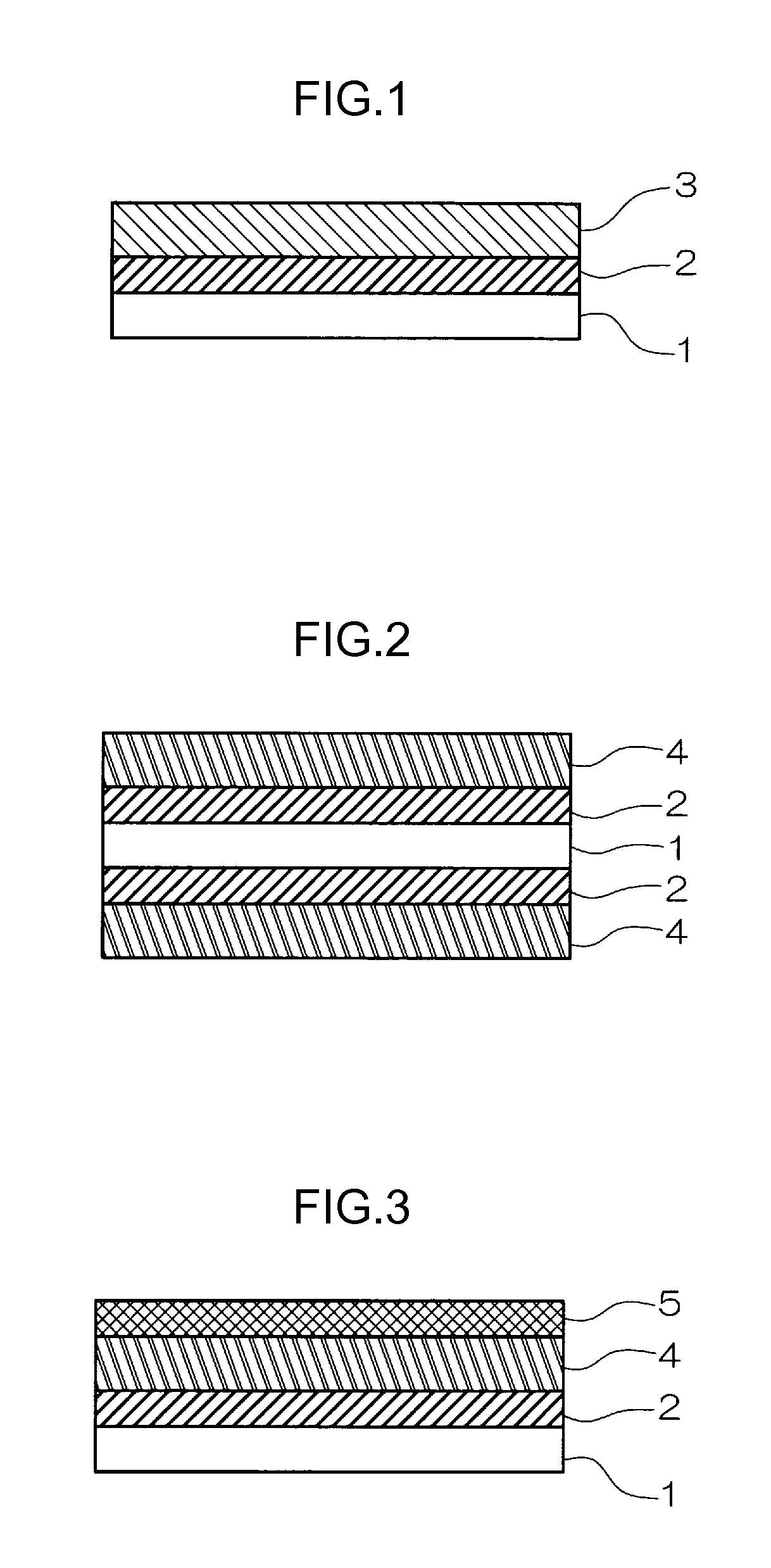
[0123]Depending on the intended object, the adhesion assist layer 2 may be compounded with various compounds in addition to the compounds described above as long as the effect of the invention is not impaired. Such additives include, for example, substances such as rubber and SBR latex capable of relaxing stress during heating, as well as compounds for improving film properties, such as a binder, a plasticizer, a surfactant and a viscosity regulator.

Problems solved by technology

However, a metal-coated resin substrate having a resin varnish layer formed on a metal foil, or a laminate having a thermoplastic layer formed between a metal foil and an insulating resin film, has a problem that when fine wirings are to be formed, fine wirings cannot be formed due to uneven surface attributable to the metal foil.
On the other hand, when the unevenness of the copper foil is reduced, there is a problem that sufficient adhesion between the metal layer and the insulating resin film cannot be attained.
In the method of arranging a feed layer by metal sputtering or vapor deposition, a metal layer is arranged on a smooth surface and thus fine wirings can be easily formed, but the adhesion between a metal and an insulating resin film is not sufficient, and production thereof requires large vacuum facilities, the operation is complicated, the forming speed is low, so the yield is low and the costs are high.
Since a hole for the connection between circuits of both sides is made after formation of a metal layer on the whole surface, a connection in the hole by plating is separately necessary, and a metal layer by plating should be formed on the previously formed metal layer, thereby making the metal layer thicker than necessary and thus necessitating long etching time in forming the circuit.
As described above, when a wiring pattern is formed on a substrate or an insulating resin film, the adhesion between the insulating resin film and the wiring pattern becomes problematic.
However, when the surface of the copper foil is made uneven for increasing adhesion by an anchor effect, it is necessary that as the distance between wirings decreases, the unevenness is decreased to such an extent that the shape of wirings is not influenced, so there is a problem that sufficient adhesion cannot be achieved.
On the other hand, the method of forming copper on polyimide by sputtering does not attain sufficient adhesion and the film making speed is low, and thus there is a problem that the cost is increased.
To solve this problem, there is a proposed method wherein the surface of a substrate is modified by grafting with a radically polymerizable compound, thereby minimizing the unevenness of the substrate and facilitating the step of processing the substrate (for example, see Japanese Patent Application Laid-Open (JP-A) No. 58-196238), but this method requires expensive apparatuses (γ-ray generator, electron beam generator).
The substrate used is a usual commercial plastic substrate, and thus the graft polymer is not sufficiently generated to such an extent that a conductive material is strongly adhered thereto, so there is a problem that the adhesion between a substrate and a conductive layer does not reach practical strength.
Under the conditions described therein, however, practically satisfactory interaction is not formed in the phenomenon of particle aggregation by the electrostatic force between the charged polymer and charged particles, so there is further demand for improvement in practical adhesion to conducive materials.
In formation of such surface graft polymers, a step of applying energy to monomer components as the starting material of graft polymers while the monomer components are contacted with the surface of a substrate is necessary, but there is a problem that it is difficult to maintain uniformity in the step, such as uniform contact and uniform energy application.

Method used


Image

  • Conductive substance-adsorbing resin film, method for producing conductive substance-adsorbing resin film, metal layer-coated resin film using the same, and method for producing metal layer-coated resin film
  • Conductive substance-adsorbing resin film, method for producing conductive substance-adsorbing resin film, metal layer-coated resin film using the same, and method for producing metal layer-coated resin film
  • Conductive substance-adsorbing resin film, method for producing conductive substance-adsorbing resin film, metal layer-coated resin film using the same, and method for producing metal layer-coated resin film

Examples


embodiment (

2-2) wherein both the polymerization modes are radical polymerization

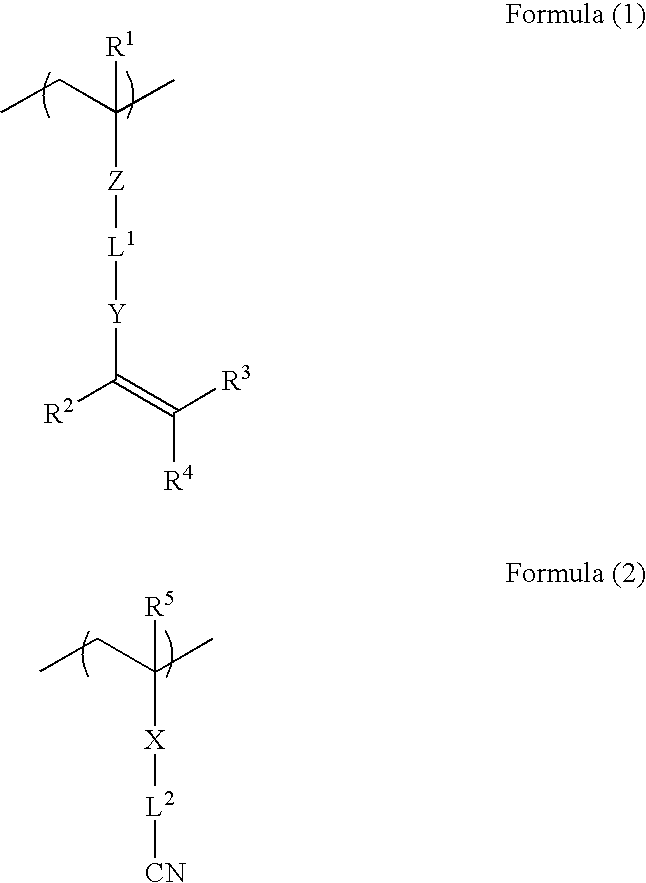
[0202]In the embodiment wherein both the polymerization modes are radial polymerization, the synthesis method may be a method (i) wherein a monomer having a cyano group is copolymerized with a monomer having a polymerizable group, a method (ii) wherein a monomer having a cyano group is copolymerized with a monomer having a double bond precursor and then treated with a base or the like to introduce a double bond into the product, and a method (iii) wherein a polymer having a cyano group is reacted with a monomer having a polymerizable group thereby introducing a double bond (introducing the polymerizable group) into the polymer. Among these methods, the method (ii) wherein a monomer having a cyano group is copolymerized with a monomer having a double bond precursor and then treated with a base or the like to introduce a double bond into the product and a method (iii) wherein a polymer having a cyano group is reacted...

example 1

Synthesis of Polymer P1 Having Polymerization Initiation Groups

[0349]30 g of propylene glycol monomethyl ether (MFG) was introduced into a 300-mL three-neck flask and then heated to 75° C. A solution consisting of 8.1 g of [2-(acryloyloxy)ethyl](4-benzoylbenzyl)dimethyl ammonium bromide, 9.9 g of 2-hydroxyethyl methacrylate, 3.5 g of isopropyl methacrylate, 0.43 g of dimethyl-2,2′-azobis(2-methylpropionate), and 30 g of MFG was added dropwise over 2.5 hours thereto. Thereafter, the reaction temperature was increased to 80° C., and the mixture was further reacted for 2 hours, to yield polymer P1 having polymerization initiation groups.

Formation of Adhesion Assist Layer 2 Containing an Initiator

[0350]20 parts by weight (hereinafter, compounding amounts are expressed in parts by weight) of bisphenol A type epoxy resin (trade name: Epicoat 828, epoxy equivalent 185, manufactured by Yuka-Shell Epoxy Co., Ltd.), 45 parts of cresol novolac type epoxy resin (trade name: Epiclon N-673, epoxy...

example 2

[0356]A conductive substance-adsorbing resin film in Example 2 was formed in the same manner as in Example 1 except that for the polyimide film that is a resin film in Example 1, a film having a hole of 200 μm in diameter formed by drilling was used as a resin support 1.


PUM

PropertyMeasurementUnit
Adhesion strengthaaaaaaaaaa
Molecular weightaaaaaaaaaa
Electrical conductoraaaaaaaaaa

Abstract

The invention provides a conductive substance-adsorbing resin film on which a conductive layer being excellent in adhesion to the resin film and having less unevenness at the interface with the resin film can easily be formed, a method for producing the same, a metal layer-coated resin film on which a high definition wiring excellent in adhesion to the insulating resin film can easily be formed, which is obtained by using the conductive substance-adsorbing resin film of the invention, and a method for producing a metal layer-coated resin film that is a material capable of easily producing a printed-wiring board having a high definition wiring. The invention also provides a conductive substance-adsorbing resin film including at least two resin layers, wherein at least one of the resin layers is an adsorbing resin layer having a property of adsorbing a conductive substance or a metal. This conductive substance-adsorbing resin film is allowed to adsorb a metal and subjected to plating, whereby a metal layer-coated resin film can be obtained.

Description

TECHNICAL FIELD[0001]The present invention relates to a conductive substance-adsorbing resin film, a method for producing the same, a metal layer-coated resin film obtained by using the conductive substance-adsorbing resin film and a method for producing the same, and in particular, to a conductive substance-adsorbing resin film useful in preparing a metal layer-coated resin film used in preparing a flexible printed-wiring board having a high-density wiring used in the field of electronic materials, a method for producing the same, a metal layer-coated resin film obtained by using the same, and a method for producing the same.BACKGROUND ART[0002]In recent years, the high-density integration of electronic parts and high-density mounting etc. have been advancing along with demand for highly advanced functions of electronic devices, and printed wiring board for high-density mounting used therein is also becoming down-sized and highly densified.[0003]Among them, a metal layer-coated res...

Claims


Application Information

Patent Timeline
IPC IPC(8): B01J20/26B32B37/14B32B38/04
CPCC23C18/30H05K3/387H05K2203/121C23C18/1641C23C18/208C23C18/285H05K3/105H05K1/0393C25D5/56C23C18/26C23C18/24C23C18/2086H05K2203/1157C23C18/1658C23C18/1653Y10T156/1062Y10T156/1052H05K2203/1105H05K3/426C23C18/206
Inventor TSURUMI, MITSUYUKIUEKI, SHIKI
Owner FUJIFILM CORP
Learn More