
High performance multilayer electrodes for use in reducing gases

a multi-layer electrode and gas reduction technology, applied in the field of planar electrochemical cells, can solve the problems of difficult scaling to higher power (more than 100 watts), low volumetric or gravimetric power density of conventional tubular cells,

Inactive Publication Date: 2009-06-11
NEXCERIS INNOVATION HLDG LLC
View PDF32 Cites 32 Cited by
  • Summary
  • Abstract
  • Description
  • Claims
  • Application Information

AI Technical Summary

Benefits of technology

"The patent text discusses materials and fabrication processes for planar electrochemical cells, specifically solid oxide fuel cells. The invention aims to provide high-stability, high-efficiency operation, sulfur tolerance, and high volumetric and gravimetric power densities of stacks of planar cells. The technical effects of the invention include improved performance and reliability of fuel cells for portable power generation and combined heat and power systems. The invention also addresses the challenge of achieving high power generation efficiency and reducing emissions of pollutants and greenhouse gases in fuel cells that use fossil fuels. The key to successful development of solid oxide fuel cells is the electrochemical cell design and \"Stacking\" configuration, which requires maximizing the active area for electrochemical reactions within the smallest volume possible. The various cell and stack design alternatives are discussed in the patent text."

Problems solved by technology

However, the operation of PEM fuel cells with fossil-based hydrocarbon fuels requires extensive pre-processing (reforming) to convert the hydrocarbons into a hydrogen rich gas and subsequent gas purification steps to reduce carbon monoxide and sulfur to very low levels (CO2S<10 ppb).
Conventional tubular cells typically suffer from low volumetric or gravimetric power density because large tubes do not pack well and have a low surface area to volume ratio.
Power densities achievable with conventional tubular cells also are limited by the long current collection paths intrinsic to long-length tubular cells.
However, microtubular cells require complex manifolding and electrical interconnection schemes so that scaling to higher powers (more than about 100 watts) is difficult.
However, anode-supported cells are not without drawbacks.
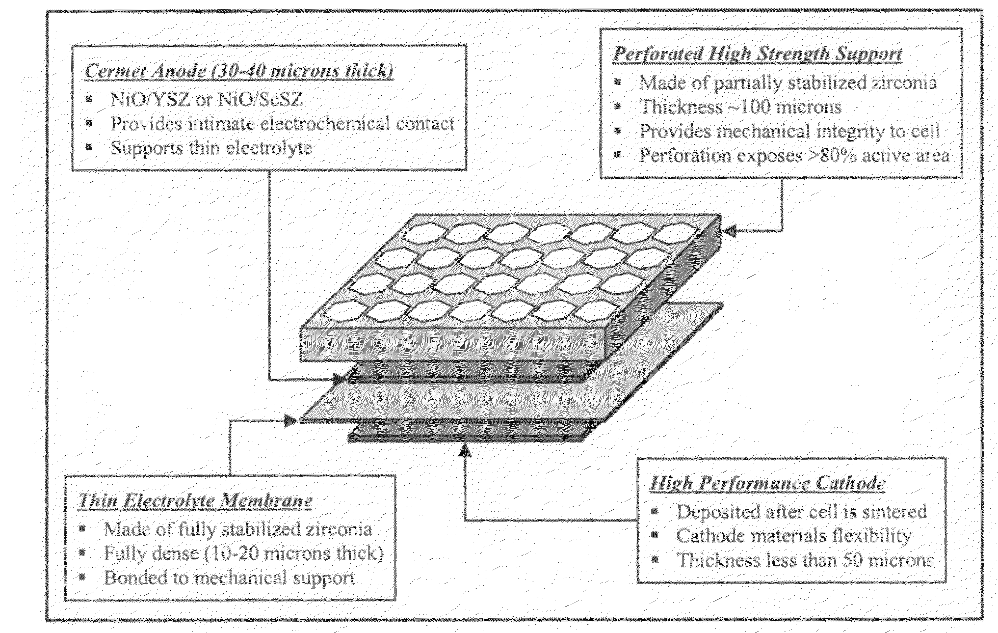
When conventional nickel oxide / yttrium-stabilized zirconia (NiO / YSZ) composites are used as support materials, the reduction of NiO to nickel metal creates stress in the electrolyte layer, which may result in considerable deformation of the support.
Operating planar anode-supported cells at high power density and high fuel use also is difficult; the thick porous layer prevents rapid diffusion of steam away from the electrolyte and results in increased cell area-specific resistance (ASR) at high current density.
Because only a thin layer of anode is affected by the reduction process, this process generally has little impact on cell mechanical stability.
The higher operating temperature of the electrolyte-supported cells can be a drawback, particularly for developers wishing to use metallic interconnect materials.
However, traditional fuels contain some level of sulfur.
Sulfur can have devastating effects on conventional SOFC performance.
Cermet mixtures of nickel metal with electrolyte materials (YSZ or GDC) are the most common SOFC anodes, but are susceptible to sulfur poisoning in concentrations as low as a few ppm.
This leads to significant performance degradation, especially at lower operating temperatures (700-800° C.) which are desired for SOFC stacks that use inexpensive metallic interconnect components.
Desulfurizers are being developed to protect fuel cell anodes from sulfur but they are too large, heavy and complex for many applications, accounting for 10-50% of total system weight, depending on the targeted fuel and useful desulfurizer life.
Additionally, desulfurizers add cost and maintenance requirements to SOFC systems.
However, these alloys do show a tendency for chrome evaporation during SOFC operation, with chrome migrating to the cathode material and causing deterioration of cathode performance.

Method used


Image

  • High performance multilayer electrodes for use in reducing gases
  • High performance multilayer electrodes for use in reducing gases
  • High performance multilayer electrodes for use in reducing gases

Examples


example 1

[0079]Nickel cobalt oxide solid solution powder was prepared for subsequent use in anode formulations described in Examples 5, 6, 11, 12, 14, 16, and 17. The first step was the preparation of a mixture that contained 112.5 grams nickel oxide (NiO) and 37.50 grams cobalt oxide (Co3O4), corresponding to a batched stoichiometry of (Ni0.76Co0.24)O . This mixture was ball milled in acetone with zirconia grinding media and the resulting slurry was dried to a powder. The dried powder mixture was calcined at 1000° C. and then sieved through a 35-mesh sieve. During calcination, the nickel and cobalt oxides reacted to form a (Ni0.76Co0.24)O solid solution powder, as confirmed by x-ray diffraction data in FIG. 14. To determine the effect of reduction on the crystal structure, a sample of the calcined (Ni0.76Co0.24)O powder was reduced in hydrogen at 800° C. and analyzed by x-ray diffraction (also shown in FIG. 14). These XRD data confirm that the reduced powder is an alloy of nickel and cobalt...

example 2

[0081]NiO—CoO solid solution powder (Ni0.76Co0.24O) containing a small amount of nanoscale samarium-doped ceria (SDC-15, Ce0.85Sm0.15O1.925) was prepared for subsequent use in anode formulations described in Examples 6, 8, 10, 11, and 15. The first step was the preparation of a mixture that contained 112.5 grams nickel oxide (NiO), 37.50 grams cobalt oxide (Co3O4), and 3 grams nanoscale SDC-15 powder having a surface area of 195 m2 / gram. This mixture was ball milled in acetone with zirconia grinding media and the resulting slurry was dried to a powder. The dried NiO—CoO / SDC powder was calcined at 1000° C. then sieved through a 35-mesh sieve to complete preparation of the coarse NiO—CoO / SDC precursor powder. Fine NiO—CoO / SDC precursor powder was made by the same initial procedure but after calcination the NiO—CoO / SDC powder was vibratory milled in acetone with zirconia grinding media to reduce its particle size. The vibratory milled NiO—CoO / SDC slurry then was dried to complete prepa...

example 3

[0082]NiO—CoO solid solution powder (Ni0.76Co0.24O) containing small amounts of nanoscale samarium-doped ceria (SDC-15) and nanoscale zirconium-doped ceria (ZDC-50, Ce0.5Zr0.5O2) powders was prepared for subsequent use in an anode formulation described in Example 9. The first step was the preparation of a mixture that contained 112.5 grams nickel oxide (NiO), 37.50 grams cobalt oxide (Co3O4), 1.5 grams nanoscale SDC-15 powder with a surface area of 195 m2 / gram, and 1.5 grams nanoscale ZDC-50 powder with a surface area of 81 m2 / gram. This mixture was ball milled in acetone with zirconia grinding media and the resulting slurry was dried to a powder. The dried powder mixture then was calcined at 1000° C. then sieved through a 35-mesh sieve. The calcined NiO—CoO / SDC / ZDC powder constituted the coarse NiO—CoO / SDC / ZDC precursor powder. Fine NiO—CoO / SDC / ZDC precursor powder was made by the same initial procedure but after calcination the NiO—CoO / SDC powder was vibratory milled in acetone wi...


PUM

PropertyMeasurementUnit
temperatureaaaaaaaaaa
areaaaaaaaaaaa
areaaaaaaaaaaa

Abstract

Electrode materials systems for planar solid oxide fuel cells with high electrochemical performance including anode materials that provide exceptional long-term durability when used in reducing gases and cathode materials that provide exceptional long-term durability when used in oxygen-containing gases. The anode materials may comprise a cermet in which the metal component is a cobalt-nickel alloy. These anode materials provide exceptional long-term durability when used in reducing gases, e.g., in SOFCs with sulfur contaminated fuels. The cermet also may comprise a mixed-conducting ceria-based electrolyte material. The anode may have a bi-layer structure. A cerium oxide-based interfacial layer with mixed electronic and ionic conduction may be provided at the electrolyte / anode interface.

Description

CROSS-REFERENCE TO RELATED APPLICATIONS[0001]Not applicable.STATEMENT REGARDING FEDERALLY SPONSORED RESEARCH[0002]Not applicable.REFERENCE TO MICROFICHE APPENDIX[0003]Not applicable.FIELD OF THE INVENTION[0004]This invention relates to materials and fabrication processes for planar electrochemical cells. The disclosed materials and processes are particularly well suited to applications in which high long-term stability, high efficiency operation, sulfur tolerance and / or high volumetric and gravimetric power densities of stacks of planar cells are desirable. This invention may be useful in electrochemical gas separation systems and catalytic reactors, including but not limited to solid oxide fuel cells for producing power from hydrocarbons and hydrogen-containing fuels, solid oxide electrolysis systems for producing hydrogen or other fuels from steam or other feedstocks, and ceramic oxygen generation systems for producing pure oxygen from air or another oxygen-containing gas.BACKGROU...

Claims


Application Information

Patent Timeline
Patent Type & Authority Applications(United States)
IPC IPC(8): H01M8/10H01M4/58
CPCH01M4/8657H01M4/8807H01M4/8885H01M4/9066H01M8/1213H01M8/124Y02E60/525H01M8/22H01M2004/8684H01M2300/0074H01M2300/0077H01M2300/0091Y02E60/521H01M8/126H01M4/8621Y02E60/50Y02P70/50H01M2008/1293
Inventor DAY, MICHAEL J.SWARTZ, SCOTT L.SEABAUGH, MATTHEW M.MATTER, PAUL H.ARCHER, JARED R.
Owner NEXCERIS INNOVATION HLDG LLC
Learn More