
Foam Production Method

Inactive Publication Date: 2008-03-20
OJI PAPER CO LTD
View PDF5 Cites 27 Cited by
  • Summary
  • Abstract
  • Description
  • Claims
  • Application Information

AI Technical Summary

Benefits of technology

[0044] According to the present invention, in the microcellular foams having a cell diameter of 10 μm or less and even in those having a cell diameter of 1 μm or less, there is an advantage in that control of foam structure and shape in microcellular foams, which have a desired thickness, shape, and foam structure, can be readily and stably achieved. In addition, according to the highly-functional microcellular foams, which are obtained due to the present invention and are not conventionally available, materials can readily be produced in which, in addition to effects to suppress reductions in mechanical strength of foams, effects to reduce sink / warp of fabricated products by injection molding or the like, and effects to improve dimensional stability, characteristics of foams such as light reflection / scattering characteristics, dielectric characteristics, and insulating characteristics are flexibly controlled. Thus, according to the present invention, there is an advantage in that great contributions are made in various fields such as packaging materials or construction materials, medical materials, materials for electrical apparatus, electronic information materials, and automobile materials. Moreover, in accordance with cell distribution, in each of the above usage, it is possible to provide highly-functional microcellular foams in which distributions of foaming characteristics are generated. Furthermore, there is also an advantage in that light guiding bodies used in liquid-crystal display apparatuses can be produced in a simple producing step.

Problems solved by technology

In the batch method, there is a problem in that extended periods of time are required for gas impregnation until saturation is reached.
For example, there is a report stating that it takes a few days in order to impregnate and to saturate carbon dioxide in polyethylene terephthalate and this poor manufacturing efficiency has been a problem.
Accordingly, even if short impregnation time is achieved, since outgassing phenomena where part of gas impregnated in a plastic under a high-pressure state is dissipated from the plastic surface in a large amount during the pressure-reducing step before foaming occurs, it becomes difficult to achieve a high degree of supersaturation, which is effective for foaming, and thus difficult to achieve cell refinement.
In the batch method, a dilemma, which emanates from the basic principle, exists between cell refinement and poor manufacturing efficiency.
However, it is said that in these methods, it is difficult to maintain a high supersaturated state at the foaming step and to make the cell diameter in the order of a few tens of microns or less.
From the reasons described so far, it is difficult to practically achieve foams having a thickness of 100 μm or less and cell diameter of 1 μm or less with the MCP foaming method.
However, when foaming at normal pressure, there were cases where obtaining thin SMCP, which had a cell diameter of 1 μm or less and also a thickness of 100 μm or less, was difficult depending on the types of foamable compositions or where the extent of deformation due to foaming became too large and maintenance of desired foaming shape became difficult.
Additionally, there were also cases where production of thick SMCP, which had a cell diameter of 1 μm or less and also a thickness of 100 μm or more, was difficult and the formation of foams on substrates and base plates; formation of foams which have a multilayer laminated structure of two or more layers; and formation of foams with complex shapes which do not have a relatively simple structure such as sheet-like, film-like, fiber-like, and rod-like shapes were difficult.
However, neither of the methods were capable of freely and flexibly controlling cell density, cell patterns, or the like.
However, in reality, it is difficult to change particle diameter or density distribution of light-scattering particles.
As the usage of liquid-crystal display apparatuses or the like become diverse, quality items required for light guiding bodies are also becoming strict.
Although specifically speaking, the forming is carried out by injection molding, since the filling rate and transfer accuracy to a die deteriorates (due to limits in resin fluidity) as light guiding bodies get thinner, it was difficult to fabricate light guiding bodies with a thickness of 1 mm or less.
However, a specific dispersion method to achieve such hole diameter and density is not described in the document and in reality, there was no method to produce such light guiding bodies.
In any of the methods described above, there was a limit in thinning of light guiding bodies of a light-scattering type.
Moreover, when the light guiding body of a light-scattering type is configured so as to house a reflecting sheet, light guide plate, prism, or the like by laying one on another in a box-shaped enclosure, mere housing results in generation of gaps between each of the optical members and light leakage could not be suppressed completely.
For this reason, there was also a limit in improving light utilization efficiency.
In addition, since the light guiding body is configured using numerous members, there was also a problem of productivity.

Method used

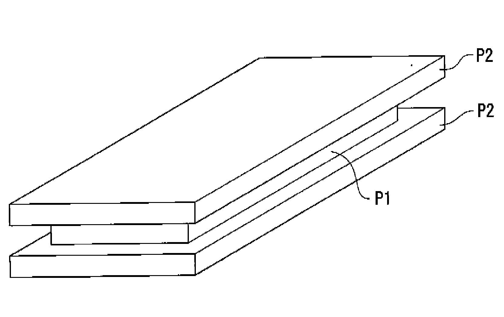
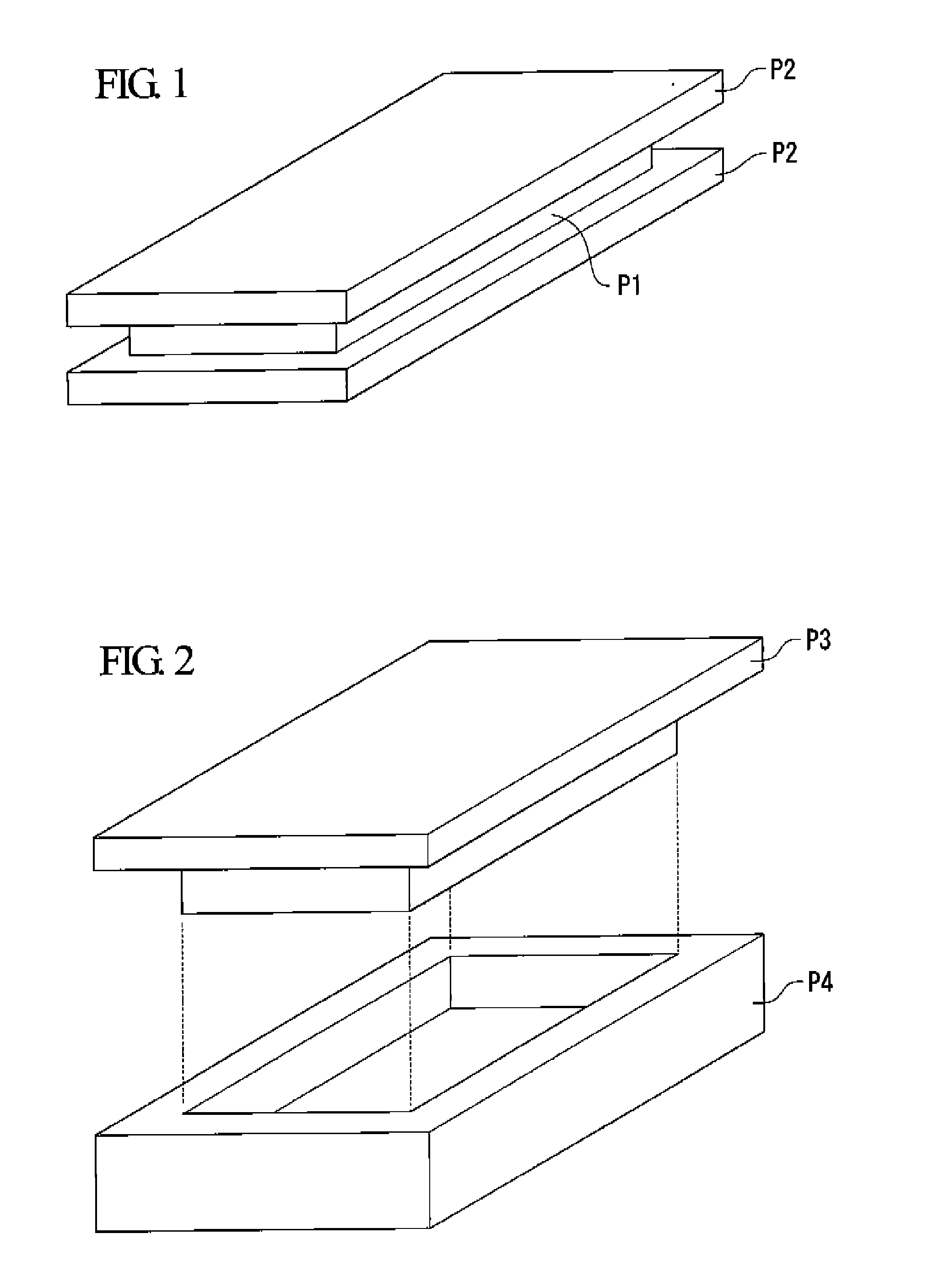
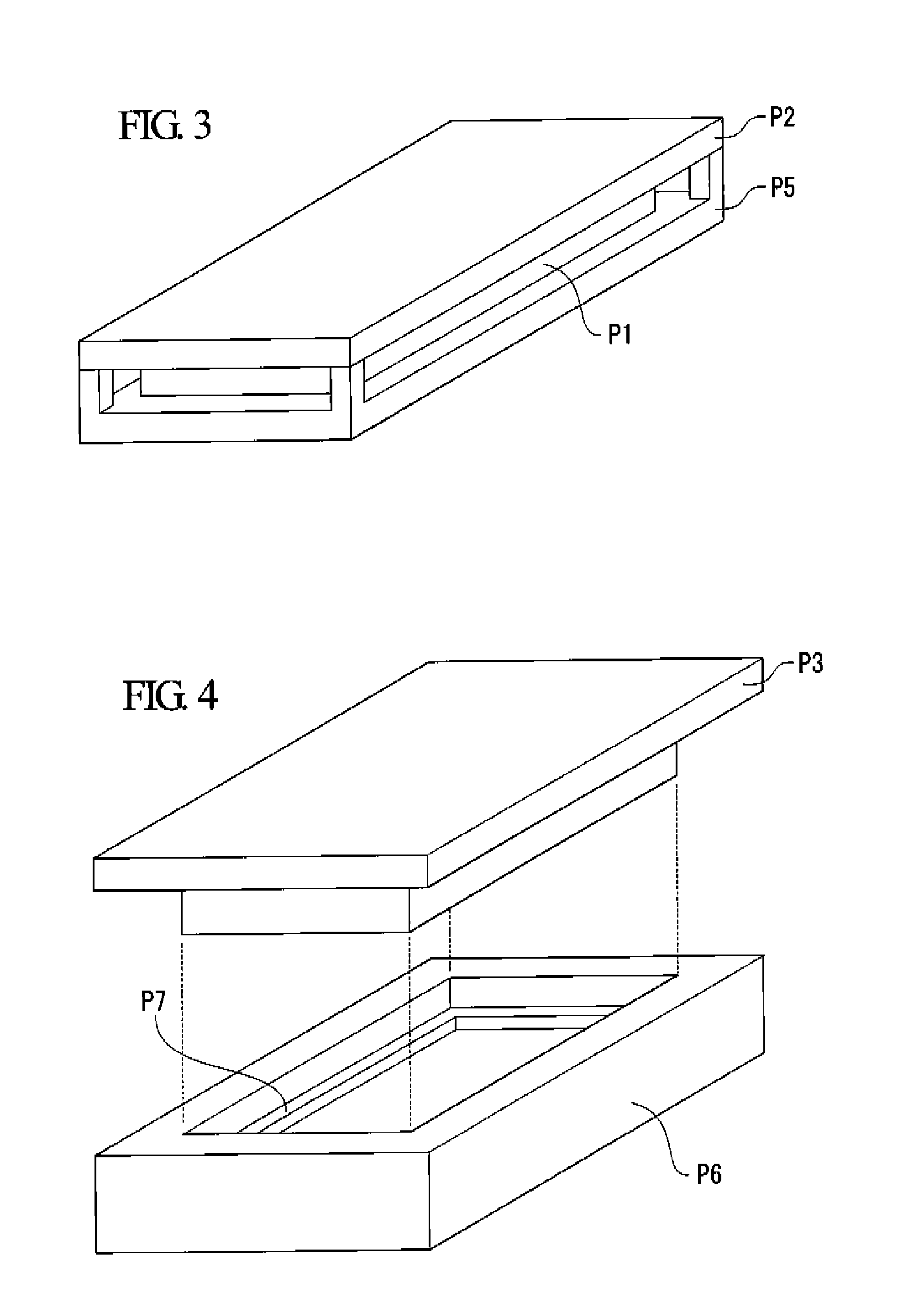

Image

  • Foam Production Method
  • Foam Production Method
  • Foam Production Method

Examples


example 1

(1) Foamable Composition

[0326] A foamable composition A where 100 parts of a copolymer (as a decomposable compound) which was composed of tert-butylacrylate (20%), tert-butylmethacrylate (40%), and methyl methacrylate (40%) were mixed with 3 parts of bis(4-tert-butylphenyl)iodonium perfluorobutanesulfonate (trade name: BBI-109 manufactured by Midori Kagaku Co., Ltd.) as an iodonium salt-based acid generating agent, was used.

(2) Preforming Step

[0327] A diluted solution of MEK / ethyl acetate with a ratio of 65 / 35 (mass ratio) was used to prepare a 25% solution of the foamable composition having the aforementioned mixed ratio and this resulting solution was used as a coating liquid. This coating liquid was coated onto the silicone-treated surface of a supporting body, which is formed from silicone PET with a thickness of 75 μm (trade name: MR-75 manufactured by Mitsubishi Polyester Film Inc.), using an applicator having a clearance of 300 μm and the coated supporting body was left in...

example 2

[0331] Foams were produced according to the same method as that of Example 1 except that the pressure applied to the laminated sample in the foaming step was 2 MPa. The obtained cross sectional picture is shown in FIG. 6.

[0332] The same foam structure evaluation as that carried out in Example 1 showed that the obtained foam was a plate-like foam having an average cell diameter of 1.0 μm, a foaming magnification of 1.8 fold, and a thickness of 700 μm.

example 3

(1) Foamable Composition

[0333] The same one used in Example 1 was used.

(2) Preforming Step

[0334] A supporting body with a coated layer where the coated layer composed of a foamable composition having a thickness of 45 μm was present on a silicone PET was produced in the same manner as that in Example 1.

(3) Ultraviolet Ray Irradiation

[0335] The supporting body with a coated layer obtained in the aforementioned step (2) was subjected to ultraviolet-ray irradiation at an exposure of 2000 mJ / cm2 from the side to which the coated layer was attached using a metal halide lamp (trade name: multi metal lamp for ultraviolet Zion curing M03-L31 manufactured by Eye Graphics Co., Ltd.) as the light source. A film formed of a foamable composition, which is already irradiated with ultraviolet radiation, was obtained by peeling the coated layer off from the silicone PET after irradiating ultraviolet radiation.

(4) Foam Forming Step

[0336] 10 pieces of 5 cm×6 cm-sized films were cut from the fi...


PUM

PropertyMeasurementUnit
Temperatureaaaaaaaaaa
Lengthaaaaaaaaaa
Pressureaaaaaaaaaa

Abstract

A foam production method including an irradiating step in which an active energy beam is irradiated onto a foamable composition containing an acid generating agent, which generates an acid, or a base generating agent, which generates a base, due to an action of an active energy beam, and containing a compound which has a decomposable / foamable functional group, which decomposes and eliminates one or more kinds of volatile substances with a low boiling point by reacting with the acid or base; and a subsequent foaming step in which the foamable composition is foamed under controlled pressure in a temperature region where the volatile substances with a low boiling point are decomposed and being eliminated.

Description

TECHNICAL FIELD [0001] The present invention relates to a foam where a plurality of independent cells and / or a plurality of continuous cells are formed and the production method thereof and in particular relates to a production method of microcellular foams with a cell diameter of 10 μm or less, or further, 1 μm or less which has a desired thickness, shape, and foam structure. In addition, the foam obtained by the production method of the present invention is a highly-functional microcellular foam which has not been conventionally available. That is, it relates to a material where, in addition to effects to suppress reductions in mechanical intensity of foams, effects to reduce sink / warp of fabricated products by injection molding or the like, and effects to improve dimensional stability, characteristics of foams such as thermal insulation properties, low conductivity properties, light scattering properties, light reflecting properties, screening properties, whiteness, opacity, wave...

Claims


Application Information

Patent Timeline
IPC IPC(8): C08J9/00
CPCC08J9/04C08L33/04C08L2203/14G02B6/0036G02B6/0065G02B6/0041C08L2666/02C08J9/228C08J2333/04
Inventor TAKADA, TOMOYUKIKOJIMA, JUNYAJINNO, FUMIO
Owner OJI PAPER CO LTD
Learn More