
Membrane-electrode assembly, electrolytic unit using the same, electrolytic water ejecting apparatus, and method of sterilization

a technology of membrane electrolysis and electrolysis water, which is applied in the direction of energy-based chemical/physical/physico-chemical processes, crystal growth processes, disinfection, etc., can solve the problems of large amount of chlorine compound bactericides, arousing troubles, and cleaning, etc., and achieves high performance and easy production

Inactive Publication Date: 2008-03-20
INST OF NAT COLLEGES OF TECH JAPAN +1
View PDF3 Cites 52 Cited by
  • Summary
  • Abstract
  • Description
  • Claims
  • Application Information

AI Technical Summary

Benefits of technology

[0055]An object of the invention is to provide a membrane-electrode assembly with which many of those problems can be eliminated and which can be easily produced and bring about high performance. Another object of the invention is to provide an electrolytic unit and an electrolytic water ejecting apparatus both employing the assembly and a method of sterilization. The electrolytic water ejecting apparatus of the invention electrolyzes the aqueous solution as a raw material, and the electrolytic water thus yielded can be immediately ejected from the apparatus and used.
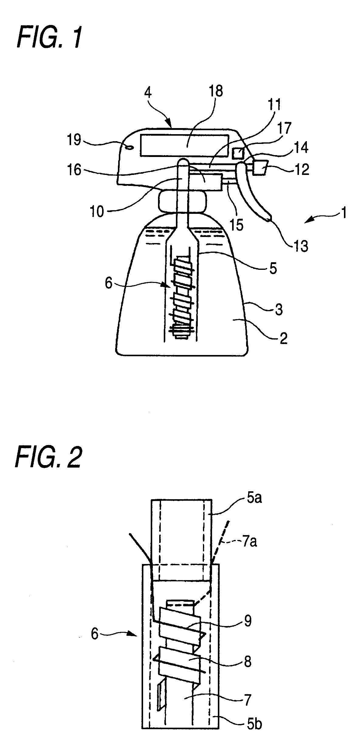
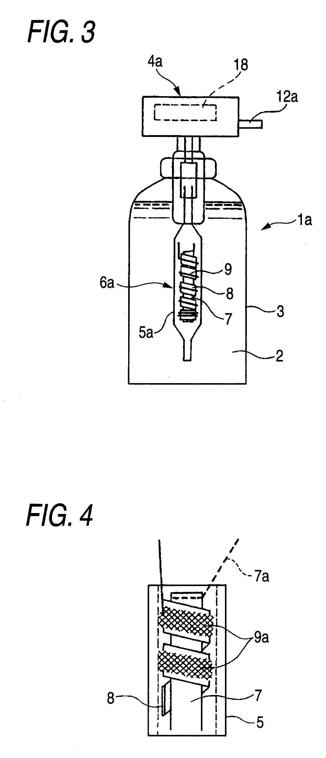
[0065]The membrane-electrode assembly of the invention comprises a rod-form or cylindrical-form electrode (hereinafter referred to as rod electrode), a strip-form diaphragm covering the periphery of the electrode, and a counter electrode disposed on the surface of the diaphragm. The surface of the diaphram on which the counter electrode is disposed is a back-side surface of a surface facing to the rod electrode. In this membrane-electrode assembly, the rod electrode, diaphragm, and counter electrode have been united together. Because of this, the assembly once produced is easy to handle. This assembly can be produced by a simple operation, e.g., by spirally winding a strip-form diaphragm and a counter electrode around the rod electrode or by covering the rod electrode with a strip-form diaphragm and a counter electrode. The term “spirally” in the invention is a general term for arrangements in which the diaphragm and counter electrode are continuously and obliquely disposed on the periphery of a rod electrode.
[0069]This membrane-electrode assembly includes a diaphragm which has been united with the other members. Because of this, by merely incorporating this assembly as it is into any desired electrolytic unit or electrolytic apparatus, the rod electrode and the counter electrode separated therefrom by the diaphragm can be mounted in the electrolytic unit or the like. Furthermore, since the two electrodes are in close contact with each other through the diaphragm, there is no need of dissolving an electrolyte in raw water for electrolysis in order to impart conductivity thereto. In addition, the voltage drop between the two electrodes is almost zero and electrolysis can be conducted at low cost.
[0077](3) High-concentration ozone-containing water (having no residual tendency, having sterilizing activity at least 10 times the sterilizing activity of hypochlorous acid systems, and further having bleaching effect; the ozone half-value period is prolonged depending on coexistent substances, resulting in improved effect retention)
[0078](4) Novel composite electrolytic water (novel sterilizing effect is produced by adding an organic acid / surfactant for pH adjustment for the purpose of improving sterilizing ability or by adding an alcohol or the like for the purpose of, e.g., improving sterilizing ability or refreshing feeling)
[0079]The membrane-electrode assembly of the invention, which comprises a rod electrode, a strip-form diaphragm covering the periphery of the electrode, and a counter electrode disposed on the surface of the diaphragm, is an assembly in which the diaphragm has been united with the two electrodes. This assembly therefore is easy to handle and can be easily mounted in various electrolytic water production apparatus.

Problems solved by technology

However, the use of chlorine compound bactericides in large amounts arouses troubles.
This cleaning, however, is regarded as problematic because it not only spoils the flavors of the food materials but also arouses a hazard (increase in THM).
However, the chemical spoils the flavor and has a residual tendency.
However, the apparatus has been unsuitable for use as a handy ozone-containing water production apparatus having excellent instant-response characteristics and yielding high-concentration ozone-containing water, for the following reasons.
(3) The power source for ozone generation has a high voltage and a high frequency, making it difficult to attain a size reduction.
(4) In the ozone-containing water production apparatus based on a discharged, a certain time period (stand-by time of several minutes) is required for the ozone gas generation ability to become stable and it is difficult to instantaneously prepare ozone-containing water having a certain concentration.
The electrolytic process is inferior to the discharge process in electric power consumption rate.
However, these electrolytes have poor handleability and are not in extensive use.
(1) When pure water, well water, or tap water is used as a raw material, the solution has high resistance and, hence, the efficiency of electrolysis is low.
(2) Although an electrolyte is usually added in order to impart conductivity, the electrodes are disposed close to each other in order to reduce the cell voltage. Because of this, the cell structure is complicated.
(3) In some applications, electrolyte addition should be avoided.
(4) Although use of an ion-exchange membrane or the like improves ionic conductivity and this is expected to increase reaction efficiency, it has been difficult to join the membrane or the like with the electrodes.
(5) The membrane usually is nonporous and is used usually in combination with porous electrodes for facilitating the feeding of an electrolytic solution and removal of products. The shapes of the electrodes are hence complicated.
(6) Although particles having an ion-exchange ability may be packed in the space between electrodes, this constitution has many limitations on assembly and structure.
(7) The porous material in a fibrous web form can also be used. However, this material has drawbacks that processing is difficult and availability is poor.
(8) In many ejecting apparatus, the pipings and members are cylindrical and, hence, the electrodes preferably are in a shape suitable therefor, i.e., in the form of a rod or cylinder. There has hence been a desire for an apparatus employing a combination of electrodes having such shape.
The fixing of the electrodes themselves is difficult.
Because this embodiment includes no diaphragm, it is difficult to closely dispose the two electrodes and this tends to necessitate a higher voltage.
Furthermore, flow rate regulation is difficult.

Method used


Image

  • Membrane-electrode assembly, electrolytic unit using the same, electrolytic water ejecting apparatus, and method of sterilization
  • Membrane-electrode assembly, electrolytic unit using the same, electrolytic water ejecting apparatus, and method of sterilization
  • Membrane-electrode assembly, electrolytic unit using the same, electrolytic water ejecting apparatus, and method of sterilization

Examples


example 1

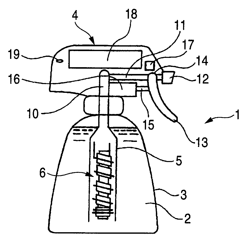
[0178]A rod made of niobium (diameter, 2 mm; length, 5 cm) on which a conductive-diamond catalyst (dopant boron concentration, 500 ppm) had been deposited was used as an anode. A strip of an ion-exchange membrane (Nafion 350, manufactured by DuPont; thickness, 0.35 mm; width, 2 mm) was spirally wound as a diaphragm around the anode. A commercial platinum wire (diameter, 0.4 mm) was wound as a cathode on the diaphragm to obtain an anode-membrane-cathode assembly. An electrolytic unit including this membrane-electrode assembly fixed therein was connected in a trigger type sprayer shown in FIG. 1 to a PE resin tube attached to the intake. A 9V prismatic battery was mounted in the head of the trigger type sprayer. In a circuit part, the electrode terminals were connected to a variable resistor and a switch with a wiring. The vessel was filled with 500 cc of pure water.

[0179]The trigger was pulled, upon which the circuit was switched on and a current flowed between the battery and the ce...

example 2

[0181]The same test as in Example 1 was conducted, except that the vessel was filled with tap water containing 0.1 g / L sodium chloride. As a result, the ozone concentration and hypochlorous acid concentration in the solution yielded were 3 ppm and 0.5 ppm, respectively (corresponding to current efficiencies of 5% and 0.3%, respectively). The terminal voltage of the cell was 7.5 V and the current was 0.4 A. The trigger operation was repeated 2,000 times. As a result, the current efficiencies for these hydrolysis products were almost the same as the respective initial values. A deposit of calcium and magnesium compounds was observed in a small amount on the cathode.

example 3

[0182]The same test as in Example 1 was conducted, except that a rod made of titanium on which an iridium oxide (5 g / m2) catalyst had been deposited was used as an anode and tap water containing 0.1 g / L sodium chloride was used. As a result, the terminal voltage of the cell was 5.5 V and the current was 0.45 A. The hypochlorous acid concentration and ozone concentration in the solution yielded were 10 ppm and 0.1 ppm or lower, respectively.


PUM

PropertyMeasurementUnit
compositionsaaaaaaaaaa
concentrationaaaaaaaaaa
pHaaaaaaaaaa

Abstract

The present invention provides: a membrane-electrode assembly having a first electrode having a shape of a rod-form or a cylindrical-form, a strip-form diaphragm covering the periphery of the first electrode, and a second electrode disposed on a surface of the strip-form diaphragm; an electrolytic unit containing the membrane-electrode assembly; an electrolytic water ejecting apparatus containing the electrolytic unit; and a method of sterilization using the membrane-electrode assembly.

Description

FIELD OF THE INVENTION[0001]The present invention relates to a membrane-electrode assembly for use in ejecting electrolytic water to be used for sterilization, cleaning, etc., an electrolytic unit structure employing the assembly, an electrolytic water ejecting apparatus (electrolytic water sprayer) employing the structure, and a method of sterilization using these.BACKGROUND OF THE INVENTIONBactericide / Disinfectant Solution[0002]Chlorine compound bactericides such as sodium hypochlorite, calcium hypochlorite, and sodium dichloroisocyanurate have been extensively used as bactericides / disinfectants in a wide range of environments. Of these, hypochlorites including sodium hypochlorite are in general use from the standpoints of cost and effect. However, many proposals have been made for attaining improvements in the bactericidal / disinfectant effect thereof which are required in various fields including the clinical field and the food industry (see, for example, JP-A-2001-253803, JP-A-2...

Claims


Application Information

Patent Timeline
Patent Type & Authority Applications(United States)
IPC IPC(8): C02F1/461C25B13/00C25B9/08C25B9/23C25B9/17C25B9/19
CPCA61L2/0088C25B13/02A61L2/183A61L2/186A61L2202/11A61L2202/15C02F1/4618C02F1/66C02F2001/46138C02F2001/46152C02F2201/003C02F2201/46115C02F2201/46125C02F2305/04C25B1/13C25B11/02A61L2/18
Inventor KITAORI, NORIYUKISEKIDO, KOTAYAMANE, GENZOHAMAGUCHI, KATSUMITANAKA, HOZUMINISHIKI, YOSHINORIFURUTA, TSUNETO
Owner INST OF NAT COLLEGES OF TECH JAPAN
Learn More