
Electrostatic chuck

a technology of electrostatic chuck and chuck body, which is applied in the direction of electrostatic holding device, basic electric elements, electric devices, etc., can solve the problems of shorting the wiring of an lsi circuit, corrosion of the structure, and deterioration of surface roughness, so as to improve the plasma resistance and fundamental functions the structure of the electrostatic chuck is small, and the effect of improving the plasma resistan

Active Publication Date: 2007-05-17
TOTO LTD
View PDF1 Cites 14 Cited by
  • Summary
  • Abstract
  • Description
  • Claims
  • Application Information

AI Technical Summary

Benefits of technology

[0016] In order to achieve the above-mentioned object, according to the present invention, there is provided an electrostatic chuck including a dielectric material in which alumina is 99.4 wt % or more, titanium oxide is more than 0.2 wt % and equal to or less than 0.6 wt %, whose average particle diameter is 2 μm or less, and whose volume resistivity is 108-1011 Ωcm in a room temperature, wherein the electrostatic chuck is used in a low temperature of 100° C. or less. With this, it is possible to improve the plasma resistance of the electrostatic chuck dielectric material and achieve fundamental functions of the electrostatic chuck at the same time.
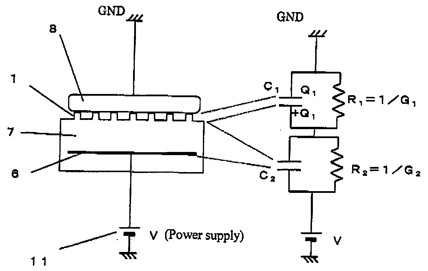
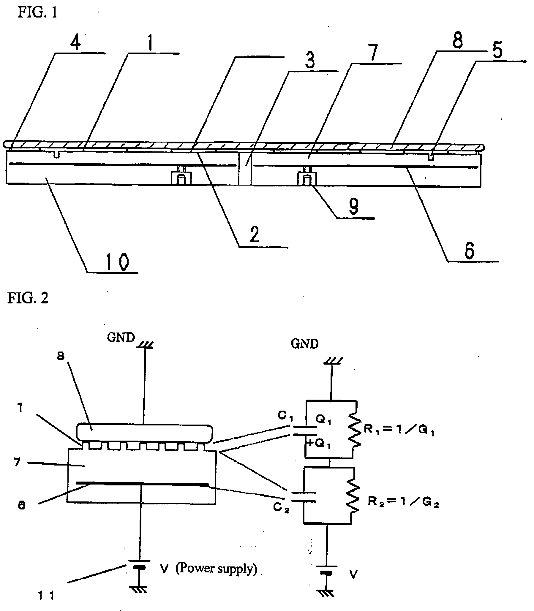
[0017] The reason why the volume resistivity needs to be 108-1011 Ωcm is for using Johnsen-Rahbeck effects as clamping force of the electrostatic chuck. It is possible to generate very great clamping force by using Johnsen-Rahbeck effects. Consequently, it is possible to reduce the contact area with a material to be clamped so as to be 1-10% with respect to the area of the clamping surface by providing protrusions on the surface of the electrostatic chuck.
[0018] Further, by adjusting the height of the protrusions provided on the surface to be 5-15 μm, it is possible to exert clamping force even in non-contact portions. As a result of this, the area of the protrusions can be 0.001% or more and less than 0.5% with respect to the area of the clamping surface. As for the temperature of the material to be clamped, heat transfer is performed via the contact portions. Consequently, even if the structure of the protrusions is subject to corrosion caused by the plasma, such effect can be reduced as the contact area of the protrusions decreases. Therefore, it is possible to achieve an electrostatic chuck in which little variations occur over time by improving the plasma-resistance and reducing the contact area with the material to be clamped.
[0021] According to another aspect of the present invention, there is provided an electrostatic chuck including a dielectric material in which alumina is 99.4 wt % or more, titanium oxide is more than 0.2 wt % and equal to or less than 0.6 wt %, whose average particle diameter is 2 μm or less, whose bulk density is 3.97 g / cm3 or more, and whose volume resistivity is 108-1011 Ωcm in room temperature, wherein the electrostatic chuck is used in a low temperature of 100° C. or less. With this, the porosity of the structure of the electrostatic chuck is small, and improvement of the plasma resistance and fundamental functions of the electrostatic chuck can be achieved at the same time.
[0022] In the above-mentioned electrostatic chuck, the dielectric material having a smooth surface includes a plurality of protrusions on which a material to be clamped is mounted, in which the ratio between the total area of the top surfaces of the protrusions and the area of the surface of the dielectric material is equal to or more than 0.001% and less than 0.5%, and the height of the protrusions is 5-15 μm. With this, it is possible to minimize the effect of variation in the clamping state caused by damage of the surface of the contact area with the material to be clamped due to corrosion by plasma. However, if the ratio of the contact area is less than 0.001%, the size of each protrusion will be too small and the processing will be difficult. If the ratio of the contact area exceeds 1%, it becomes impossible to disregard the effect of plasma corrosion to the surface of the protrusions in contact with the material to be clamped.

Problems solved by technology

However, if the ceramic structure is exposed to a plasma atmosphere, the structure is subject to corrosion, and the surface roughness is deteriorated.
Consequently, there are some cases where variations in the contact state between the surface of the electrostatic chuck and the wafer occur over time, or there are other cases where grains are disjoined from a sintered body and the disjoined grain particles cause the wiring of an LSI circuit to be shorted.
However, in this example, even if the plasma-resistance is improved, there is no description of the electrical characteristics, and it is impossible to perform fundamental functions of a Johnsen-Rahbeck electrostatic chuck which enables great clamping force.
However, in this case, it is impossible to obtain electrical characteristics for performing functions of an electrostatic chuck.
Although an additive of at least 0.5 wt % is required to reduce the volume resistivity, such an amount of the additive is too much for an electrostatic chuck which requires a strict limitation in contamination with respect to a material to be clamped.
However, there is no description of properties of an dielectric material required for an electrostatic chuck which is used in another temperature range, for example, a relatively low temperature such as 100° C. or less.

Method used


Image

  • Electrostatic chuck
  • Electrostatic chuck
  • Electrostatic chuck

Examples


Embodiment Construction

[0026] Alumina, titanium oxide, and transition metal oxide as ingredients were granulated at a mixing ratio shown in Table 1. The average particle diameter of the alumina was 0.1 μm, and the purity of the alumina was 99.99% or more. The purity of the titanium oxide was 98% or more.

Slurry Preparation, Granulation, and Raw Processing

[0027] The above ingredients were mixed at the mixing ratio shown in Table 1, and crushed. After an acrylic binder was added and adjusted, granulation by spray-drying was performed to prepare granulated powder. After the granulated powder was filled in a rubber mold, CIP (pressure: 1 ton / cm2) was performed, and an ingot was formed. The ingot was processed to have a predetermined shape, and a raw formed body was obtained. Ion-exchange water or the like was used for mixing, so that contaminants could be prevented from entering as much as possible.

Firing

[0028] The above raw formed body was fired in an atmosphere of nitrogen and hydrogen gas. The firing ...


PUM

PropertyMeasurementUnit
temperatureaaaaaaaaaa
volume resistivityaaaaaaaaaa
particle diameteraaaaaaaaaa

Abstract

The object of the present invention is to provide an electrostatic chuck in which the surface can be kept smooth after being exposed to plasma, so as to protect a material to be clamped such as a silicon wafer from being contaminated with particles, and which is excellent in clamping and releasing a material to be clamped. According to the present invention, there is provided an electrostatic chuck comprising a dielectric material in which alumina is 99.4 wt % or more, titanium oxide is more than 0.2 wt % and equal to or less than 0.6 wt %, whose average particle diameter is 2 μm or less, and whose volume resistivity is 108-1011 Ωcm in room temperature, wherein the electrostatic chuck is used in a low temperature of 100° C. or less.

Description

BACKGROUND OF THE INVENTION [0001] 1. Field of the Invention [0002] The present invention relates to an electrostatic chuck for clamping and fixing a material to be clamped such as a semiconductor wafer or a glass substrate for an FPD with electrostatic force. [0003] 2. Description of Prior Art [0004] Conventionally, a ceramic dielectric material of an electrostatic chuck is provided for the purpose of controlling the electrical characteristics (See Document 1). [0005] However, if the ceramic structure is exposed to a plasma atmosphere, the structure is subject to corrosion, and the surface roughness is deteriorated. Consequently, there are some cases where variations in the contact state between the surface of the electrostatic chuck and the wafer occur over time, or there are other cases where grains are disjoined from a sintered body and the disjoined grain particles cause the wiring of an LSI circuit to be shorted. [0006] In another conventional example, an alumina ceramic mater...

Claims


Application Information

Patent Timeline
Patent Type & Authority Applications(United States)
IPC IPC(8): H01T23/00
CPCH02N13/00
Inventor MIYAJI, JUNOKAMOTO, OSAMUKITABAYASHI, TETSUO
Owner TOTO LTD
Learn More