
Solid state, thin film proton exchange membrane for fuel cells

a fuel cell and thin film technology, applied in the field of fuel cells, can solve the problems of unsafe and impractical keeping hydrogen in liquid form, classical high pressure tanks, even tanks made of novel carbon-fiber reinforced composite materials, etc., and achieve the effects of reducing the resistance of the fuel cell, reducing the operation temperature, and increasing the power density of the fuel cell

Inactive Publication Date: 2007-02-22
KAZARINOV RUDOLF FEODOR
View PDF7 Cites 5 Cited by
  • Summary
  • Abstract
  • Description
  • Claims
  • Application Information

AI Technical Summary

Benefits of technology

[0014] The present invention relates to an article that comprises a solid oxide fuel cell having features that can result in the reduction of the operation temperature and an increase in the power density of the fuel cell. In particular, the present invention is directed to a thin film solid state fuel cell that is compatible with MgH2 hydrogen storage and is capable of operating in the temperature range of 300-400° C. In the proposed fuel cell, the thickness of the proton conductor is a fraction of a micron, allowing for a reduction of its resistance by a factor of a thousand which, in turn, allows significant increase of fuel cell power density and efficiency.
[0015] More specifically, the fuel cell of the present invention comprises a multilayer solid state structure on a metal substrate, and contacts that facilitate flowing a current through the multilayer structure. The multilayer structure comprises a metal oxide polymer protonic conductor and metal coatings on both the protonic conductor an the metal substrate. The metal substrate is made of a metal foil having high hydrogen permeability, such as niobium, vanadium or tantalum. The metal oxide polymer protonic conductor is made by electrolytic anodizing of a metal alloy film deposited on the metal substrate, for example, by co-sputtering of transitional metals having different valences. Hafnium and zirconium-doped tantalum are two such examples of such an alloy. A relatively small thickness of the protonic conductor layer (e.g., 0.1-0.5 μm) allows for a significant reduction of its resistance. This results in an increase of power density and efficiency at moderate operating temperatures. Another possibility for a metal oxide thin film protonic conduct is an ReOx film made by electrochemical deposition. The metallic coatings of the protonic conductor and the metal substrate comprise thin films of metals having a large electron work function, such as platinum, palladium or nickel. These films operate as catalysts enhancing decomposition of hydrogen and oxygen molecules into atoms. Encapsulation of the protonic conductor between the metal substrate and the metal coating also preserves high proton concentration in the conductor at elevated temperatures.

Problems solved by technology

However, the ability to safely and efficiently store hydrogen for vehicular power source application presents a formidable problem.
Classical high pressure tanks, even tanks made of novel carbon-fiber reinforced composite materials, are considered unsafe.
Keeping hydrogen stored as in liquid form is also considered to be dangerous and impractical.
However, all of these systems provide only about 2-3 wt % of hydrogen storage.
The problem here is not the temperature of the transition, but its enthalpy.
This is an unacceptable loss of energy, since a conventional combustion engine efficiency is only about 20% and fuel cells have an efficiency of 40-50%.
However, neither the combustion engine or any other known fuel cells can operate at temperatures in the range of 300-350° C.
One of the disadvantages of the Nafion PEMFC for some applications is that the operation temperature is relatively low (T<100° C.).
As a result, the fuel cell cost per unit of power is very high.
The problem with this type of fuel cell is that the by-products of the reaction dilute the fuel itself.

Method used


Image

  • Solid state, thin film proton exchange membrane for fuel cells
  • Solid state, thin film proton exchange membrane for fuel cells
  • Solid state, thin film proton exchange membrane for fuel cells

Examples


Embodiment Construction

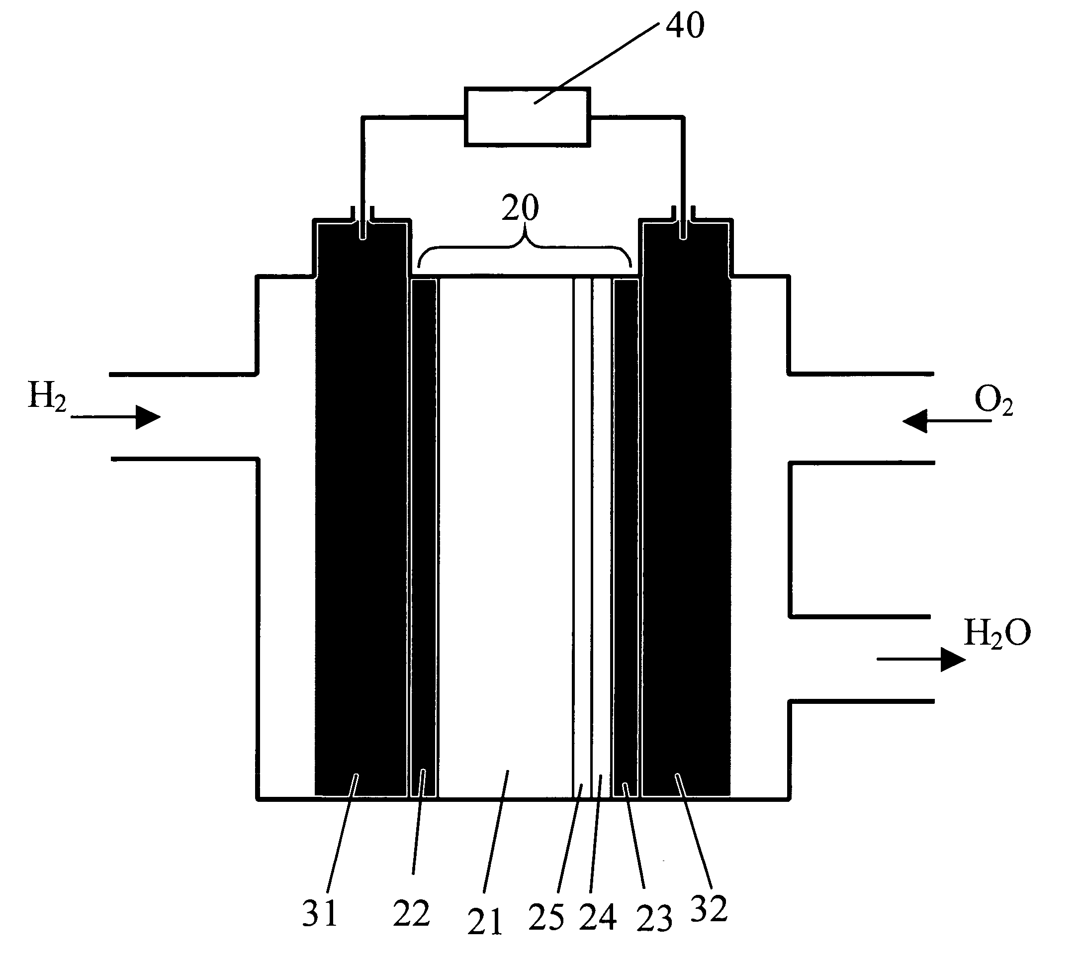
[0021]FIG. 1 illustrates, in schematic form, the relevant aspects of a fuel cell 10 formed in accordance with the present invention. Fuel cell 10 consists of a solid state multilayer structure 20 sandwiched between a pair of gas diffusion layers 31 and 32, where gas diffusion layers 31, 32 comprise porous carbide. In accordance with the present invention, multilayer structure 20 comprises a metal foil layer 21, with a metal oxide polymer (protonic conductor) 24 disposed over foil layer 21 and in contact with gas diffusion layer 31. Protonic conductor 24 functions as the solid electrolyte layer in the fuel cell structure. In accordance with the present invention, metal foil layer 21 comprises a metal with a relatively high hydrogen permeability, such as niobium, vanadium or tantalum and generally exhibits a thickness on the order of 25-250 μm. A first metallic coating layer 22 is formed over metal foil layer 21 so as to be disposed between first diffusion layer 31 and metal foil laye...


PUM

PropertyMeasurementUnit
temperatureaaaaaaaaaa
temperaturesaaaaaaaaaa

Abstract

A fuel cell according to the invention comprises a multilayer proton exchange membrane having high proton conductivity in the temperature range of 300-500° C. This is achieved by the use of very thin (<1 μm) metal oxide polymer films on a metal substrate by electrolytic anodizing of a metal alloy. An exemplary proton exchange membrane according to the invention comprises a Ta2-xHfxO5 film fabricated on a niobium foil. The invention allows for a significant increase in power density and, therefore, a significant reduction in fuel cell cost per unit power.

Description

TECHNICAL FIELD [0001] The present invention relates to fuel cells for vehicular power source applications and, more particularly, to thin film proton exchange membrane fuel cells. BACKGROUND OF THE INVENTION [0002] Since the chemical energy per mass of hydrogen (124 MJ / kg) is at least three times larger than that of other chemical fuels (for example, the equivalent value for liquid hydrocarbons is 47 MJ / kg), it is considered as the number one candidate for future car fuel. However, the ability to safely and efficiently store hydrogen for vehicular power source application presents a formidable problem. [0003] Classical high pressure tanks, even tanks made of novel carbon-fiber reinforced composite materials, are considered unsafe. Moreover, these high pressure containers, when full, would contain only approximately 4% hydrogen by mass (4 wt %), while at least 6-7 wt % hydrogen is required by the US Department of Energy (DOE) standards. Keeping hydrogen stored as in liquid form is a...

Claims


Application Information

Patent Timeline
Patent Type & Authority Applications(United States)
IPC IPC(8): H01M8/02H01M8/10
CPCH01M4/94H01M8/0234H01M8/1053H01M8/1055H01M8/1086H01M8/1246H01M2300/0094Y02E60/525Y02P70/56Y02E60/50Y02P70/50
Inventor KAZARINOV, RUDOLF FEODOR
Owner KAZARINOV RUDOLF FEODOR
Learn More