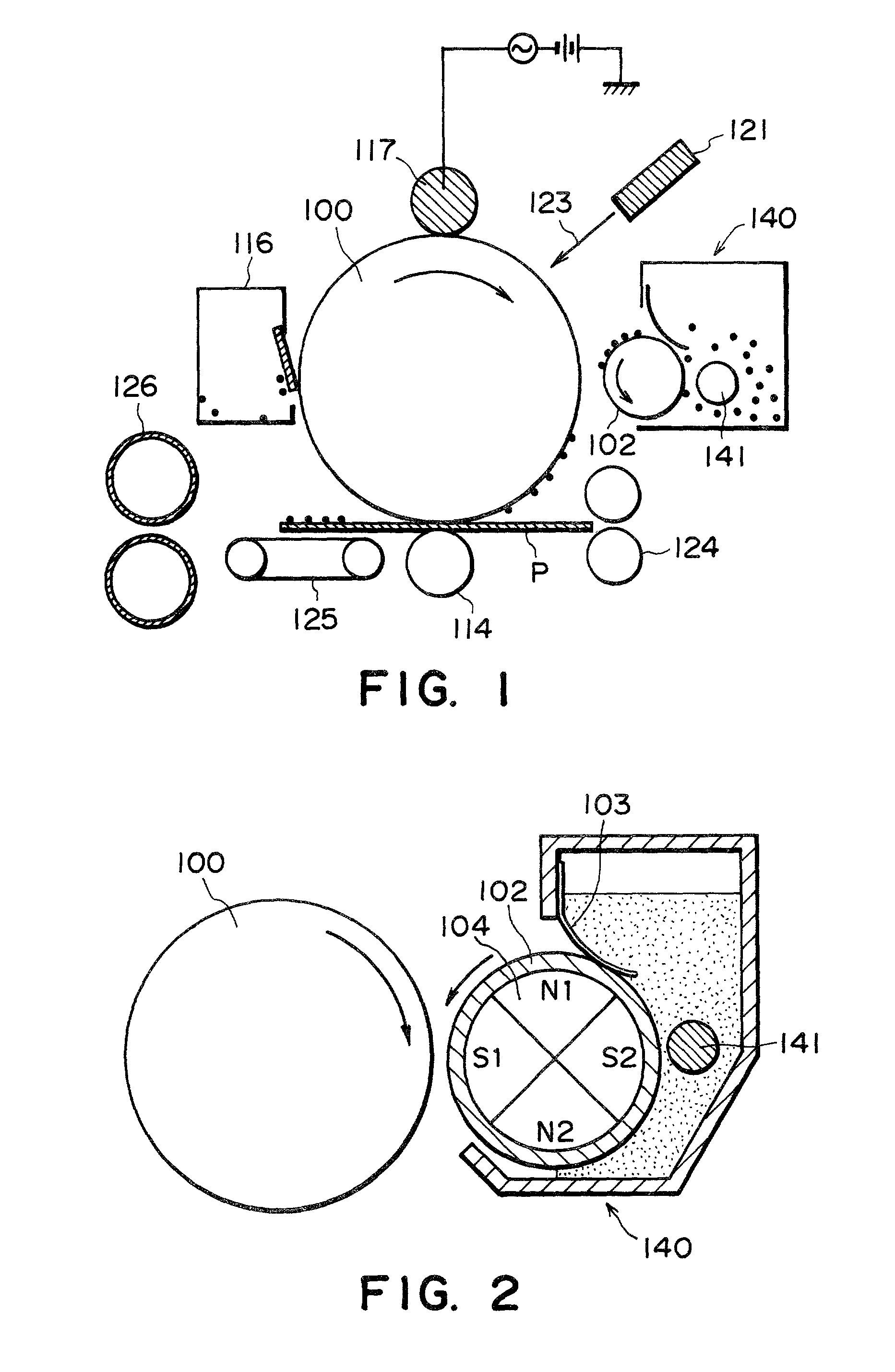
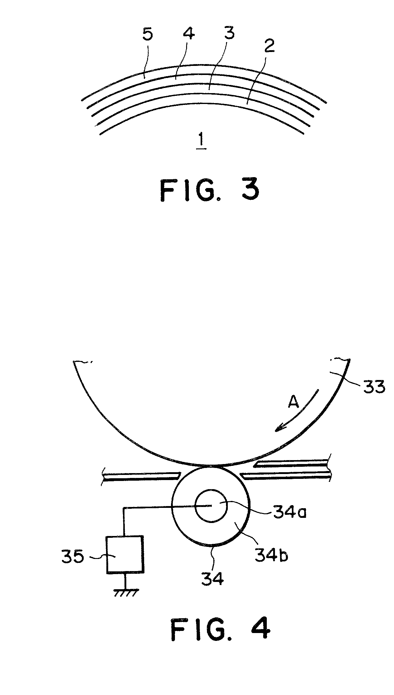
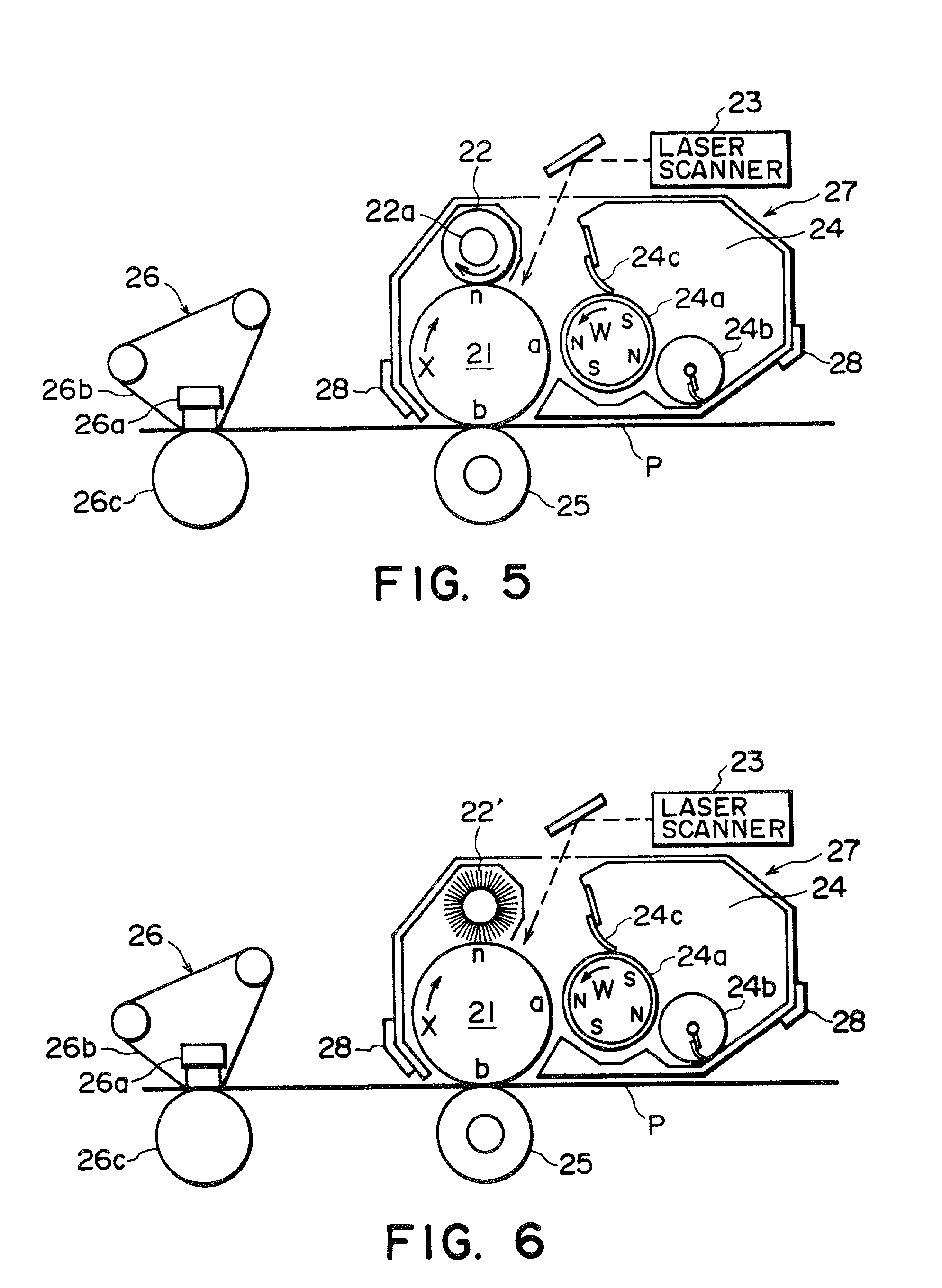
The developing method using such an electroconductive magnetic toner is an excellent method capable of obviating the problems accompanying the conventional two-component developing method, but on the other hand, involves a problem that it becomes difficult to effect the transfer of a developed image from the recording member to a final supporting material, such as plain paper, because the toner is electro-conductive.
However, such a method involves essential problems of a slow developing speed or inability of obtaining a sufficiently high
image density.
This method is accompanied with a problem that the toner particles are liable to have an insufficient triboelectric charge leading to image defects due to charging failure because of a low opportunity of contact between the toner particles and the friction member and the magnetic toner particles used contain much
magnetic powder exposed to the toner particle surfaces.
However, such a developing method using an insulating magnetic toner is accompanied with uncertain factors inherent to the use of an insulating magnetic toner.
Such uncertain factors are caused by
exposure of a portion of magnetic
fine powder mixed and dispersed in a substantial amount in the insulating magnetic toner, and as a result, several performances, such as developing performance and durability, required of a magnetic toner, are changed or deteriorated.
It is considered that the above-mentioned problem encountered in the case of using a conventional magnetic toner containing magnetic
powder has been principally caused by
exposure of the magnetic
powder to the magnetic toner surface.
More specifically, if magnetic
powder having a relatively low resistivity is exposed to the surface of magnetic toner particles principally composed of a resin having a larger resistivity, toner performance lowering are caused, such as a lowering in toner chargeability, lowering in toner flowability, and a lowering in
image density or occurrence of a density irregularity called sleeve ghost caused by liberation of the magnetic powder due to friction between individual toner particles and between toner particles and the regulating member during a long term of use.
Hitherto, proposals have been made regarding magnetic
iron oxide contained in magnetic toners, but have left problems yet to be solved.
As a result of the use of a
silicate salt for particle
shape control, the magnetic
iron oxide particles contain much
silicon inside thereof and have little
silicon at the surfaces, thereby having a
smooth surface, so that the
resultant toner is caused to have somewhat improved flowability but the adhesion between the magnetic iron
oxide particles and the binder resin constituting the magnetic toner is insufficient.
The triiron tetroxide obtained through this process retains Si at proximity to its surface, but the Si is present in a layer
proximate to the surface, so that the surface thereof is weak against a
mechanical impact such as abrasion.
As a result of providing a fragile colorant-dispersed resin from this requirement, an actual high-speed pulverization of the colorant-dispersed resin is liable to result in particles of a broad particle size range, particularly including a relatively large proportion of
fine powder fraction (excessively pulverized particles).
Moreover, a toner of such a highly fragile material is liable to be further fine pulverization or powder formation during its use as a developer in a
copying machine, etc.
Further, according to toner production by the pulverization process, it is difficult to completely uniformly disperse
solid particles, such as magnetic powder or colorant into a resin, and a
lower degree of dispersion is liable to result in increased
fog and a lower
image density.
Further, the pulverization process essentially and inevitably results in
exposure of magnetic iron
oxide particles to the toner particle surfaces, thus leaving problems regarding toner flowability and charging stability in a severe environment.
Thus, the pulverization process essentially poses a limit in production of small-size toner particles required for
high resolution and high-quality images, as it is accompanied with inevitable problems regarding uniform chargeability and flowability of the toner.
Accordingly, in case where
magnetite of smaller particle size exhibiting a higher coloring power is used, the
magnetite is liable to cause magnetic agglomeration during toner production, thus leaving problems in developing performance in some cases.
Moreover, the
residual magnetization of the
resultant toner particle is increased, so that the toner particles are liable to exhibit a lower flowability also due to magnetic agglomeration or a lower developing performance due to an increased magnetic constraint force exerted from the sleeve in the magnetic mono-component developing method.
Moreover, during the continued use for a long period, a portion of the toner exhibiting a relatively low developing performance is gradually accumulated without being consumed for development, various problems, such as image density lowering occur.
The toners disclosed in these publications are however pulverization toners, and are therefore accompanied with difficulty in suppressing the exposure of the magnetic powder to the toner particle surfaces, so that they are accompanied with problems in dispersibility of the magnetic powder, toner flowability, charging stability in a severe environment, a lower circularity and transferability.
Further, these publications include only Examples wherein a magnetic blade exerting less load on the toner is used as a toner
layer thickness-regulating member in the image forming apparatus, so that these publications do not clarify at all how the toner
residual magnetization affects the
image quality in the case of using a toner
layer thickness regulating member exerting a
mechanical load on the toner, such as an elastic blade abutted against a toner-carrying member, for providing an improved toner chargeability.
However, if a
polymerization toner contains magnetic powder, the flowability and the chargeability thereof are liable to be remarkably lowered.
This is because magnetic powder is generally hydrophilic and is therefore liable to be present at the toner surface.
These treatments provide a somewhat improved dispersibility in the toner but are accompanied with a problem that it is difficult to uniformly hydrophobize magnetic powder surfaces, so that it is difficult to obviate the coalescence of magnetic powder particles and the occurrence of untreated magnetic powder particles, thus being insufficient to improve the dispersibility in the toner to a satisfactory level.
However, the publication describes carbon as the colorant and does not clarify any regarding the effect in the case of using magnetic powder.
As a result, the product toner is still accompanied with problems regarding not only
odor at the time of heating but also fixability and chargeability according to our study.
The publication however does not disclose how the hydrophobization of magnetic powder was performed.
As a result, the publication does not clarify the effects in the case where toner particles are formed by
polymerization of a polymerizable mixture including magnetic powder,
styrene monomer and a
peroxide polymerization initiator.
However, no description is made regarding the production of a polymerization toner.
Thus, the publication does not clarify at all what effects are attained when the alkali treatment is applied to the production of a polymerization toner containing magnetic powder.
However, the above-mentioned various problems have not been fully solved as yet.
The
system including such a cleaning step has been generally accompanied with a difficulty that the life of the
latent image-bearing member is shortened due to abrasion caused by abutting of the cleaning member against the
latent image-bearing member.
The provision of the cleaning device results in an increase in apparatus size and has provided an obstacle against apparatus compactization.
This
system has not been satisfactory for various
recording media which are expected to receive transferred toner images in view of wide application of electrophotography in recent years.
These systems have not been described with respect to desirable image forming methods or toner compositions.
However, such a development and simultaneous cleaning system or a cleanerless system is liable to cause toner deterioration, and the deterioration or wearing of the toner-carrying member surface or photosensitive member surface, so that a sufficient solution has not been given to the durability problem.
However, based on the direct injection charging mechanism, the charging performance is affected by the contactivity of the contact charging member onto the member-to-be-charged.
Accordingly, even if the direct injection charging is intended, the lowering in charging performance, and charging irregularities due to insufficient contact, contact irregularity due to the roller shape and attachment onto the member-to-be-charged, are liable to be caused.
In the DC charging scheme, however, it has been difficult to charge the photosensitive member to a desired potential, since the resistivity of the contact charging member is liable to change in response to a change in environmental condition, and because of a change in Vth due to a
surface layer thickness change caused by abrasion of the photosensitive member.
Further, in the AC-charging scheme for uniform charging,
ozone generation is liable to be promoted, a vibration
noise (AC charging
noise) between the contact charging member and the photosensitive member due to AC
voltage electric field is liable to caused, and the photosensitive member surface is liable to be deteriorated due to the
discharge, thus posing a new problem.
100 / mm.sup.2 can be relatively easily obtained, but even at such a high
fiber density, the contact characteristic is insufficient for realizing sufficiently uniform charging according to the direct injection charging.
In order to effect a sufficiently uniform charging according to the direct injection charging, it is necessary to provide a large speed difference between the fur
brush charger and the photosensitive member, and this is not practically feasible.
The magnetic
brush charging scheme is however accompanied with difficulties that the device structure is liable to be complicated, and the magnetic particles constituting the magnetic
brush are liable to be liberated from the magnetic brush to be attached to the photosensitive member.
The contact charging scheme or the contact transfer scheme, unlike the
corona discharge scheme, is accompanied with problems.
More specifically, in the contact transfer step, the transfer member is abutted against the image-bearing member via a transfer material, so that the toner image is pressed between the image-bearing member and the transfer material by a pressing force exerted by the transfer member, thus being liable to cause a local transfer failure called "transfer (hollow) dropout".
On the other hand, in the contact charging step, the charging member is pressed against the image-bearing member surface, so that the transfer-residual toner is also pressed against the image-bearing member by the charging member, whereby the image-bearing member is liable to cause surface abrasion or wearing, and further toner melt-sticking is liable to occur at the abraded part of the image-bearing member as the nuclei.
The abrasion and toner melt-sticking on the image-bearing member result in serious defects in latent
image formation on the image-bearing member.
More specifically, the abraded part of the image-bearing member causes a primary charging failure to result in black spots in a
halftone image, and the toner melt-sticking causes an exposure failure to result in
white spots in a
halftone image.
Further, these surface defects result in poorer toner transfer.
As a result, in combination with the above-mentioned transfer failure due to the contact transfer, the image defects can be synergistically promoted.
The abrasion and transfer failure on the image-bearing member is liable to be pronounced in the case of using a developer comprising indefinite-shaped toner particles.
This is presumably because such an indefinite shaped toner is liable to scrape the image-bearing member surface in addition to its inherent lower transferability due to the shape.
Further, in case where the transfer-residual toner is increased, it becomes difficult to retain a sufficient contact between the contact charging member and the photosensitive member to result in a lower chargeability, so that in the reversal development system,
fog, i.e., toner transfer onto non-image parts, is liable to occur.
If an insulating toner is attached to or mixed into the contact charging member, the charging performance of the charging member is liable to be lowered.
On the other hand, in the charging scheme wherein the direct injection charging mechanism is predominant, the lowering in charging performance is caused as a lowering in chargeability of the member-to-be-charged due to a lowering in opportunity of contact between the contact charging member surface and the member-to-be-charged due to the attachment or mixing of the transfer residual toner particles into the contact charging member.
The lowering in uniform chargeability of the photosensitive member (member-to-be-charged) results in a lowering in contrast and uniformity of latent image after imagewise exposure, and a lowering in image density and increased
fog in the
resultant images.
However, if the transfer residual toner particles are attached to or mixed to the contact charging member in an amount exceeding the toner charge polarity-controlling capacity of the contact charging member, the charging polarity of the transfer residual toner particles cannot be uniformized so that it becomes difficult to recover the toner particles in the developing step.
Further, even if the transfer residual toner particles are recovered by a
mechanical force of
rubbing, they adversely affect the triboelectric chargeability of the toner on the toner-carrying member if the charge of the recovered transfer residual toner particles has not been uniformized.
As a result, in the case of a
continuous use of the apparatus for a long period, the defect of
image flow due to the
ozone products is liable to occur.
Further, in case where the above organization is adopted in the cleanerless image forming apparatus, the attachment of the powder onto the charging member is obstructed by mixing with transfer-residual toner particles, thus reducing the uniform charging effect.
The contact charging or proximity charging scheme used in the proposal is one relying on the
discharge charging mechanism and not based on the direct injection charging mechanism so that the above problem accompanying the discharge mechanism accrues.
Further, in case where the above organization is applied to a cleanerless image forming apparatus, larger amounts of electroconductive particles and toner particles are caused to pass through the charging step and have to be recovered in the developing step.
Further, in a case where a contact charging scheme relying on the direct injection charging scheme is adopted, the electroconductive fine particles are not supplied in a sufficient quantity to the contact charging member, so that the charging failure is liable to occur due to the influence of the transfer residual toner particles.
Further, in the proximity charging scheme, it is difficult to uniformly charge the photosensitive member in the presence of large amounts of electroconductive fine particles and transfer residual toner particles, thus failing to achieve the effect of removing the pattern of transfer residual toner particles.
As a result, the transfer residual toner particles interrupt the imagewise exposure pattern light to cause a toner particle pattern ghost.
Further, in the case of instantaneous power failure or paper clogging during
image formation, the interior of the image forming apparatus can be remarkably soiled by the developer.
This image forming method however relies on a contact charging scheme based on the discharge charging scheme and not on the direct injection charging scheme, so that the system is not free from the above-mentioned problems involved in the discharge charging mechanism.
Further, these proposals may be effective for suppressing the charging performance of the contact charging member due to transfer residual toner particles but cannot be expected to positively enhance the charging performance.
Such an image forming apparatus may exhibit a good development and simultaneous cleaning performance and remarkably reduce the waste toner amount, but liable to result in an increased production cost and a difficulty against the
size reduction.


