


Quick Research
Generate reliable direction feasibility study reports for your R&D in just a few steps.

Technical Q&A
Discover and master advanced knowledge NOW. Basics, ideas, possibilities, all at once.

Find Solutions
As an expert in R&D theories, this can generate solutions to your technical problems instantly.

Evaluate Feasibility
Analyze your overall solution with one click, know your potential R&D risks in advance.

Monitor Landscape
Get weekly tech updates, stay abreast of the latest tech innovations and key insights.
Ceramic dielectric filter surface coating method based on micro-arc ion plating and ceramic dielectric filter
A micro-arc ion plating, ceramic dielectric technology, applied in ion implantation plating, waveguide type devices, coatings, etc., can solve the problems of film breakage, insufficient film adhesion, poor diffraction, etc., to enhance the interface bonding Strength, improved film thickness uniformity, and improved bonding effect
- Summary
- Abstract
- Description
- Claims
- Application Information
AI Technical Summary
Problems solved by technology
Method used
Image

Examples
Embodiment 1
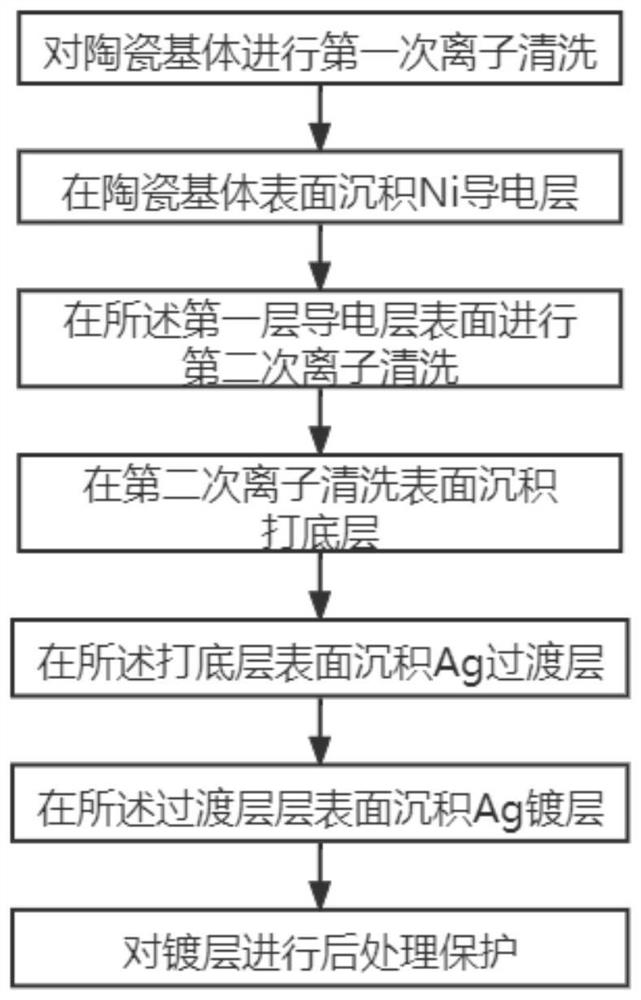
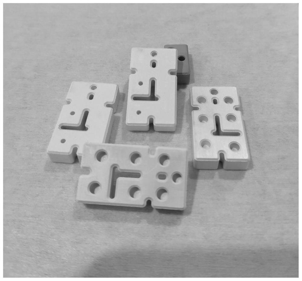
[0072] Step 1: Select the ceramic dielectric filter as the substrate, and perform conventional pre-cleaning treatment on the substrate.
[0073] Step 2: Place the ceramic dielectric filter obtained in step 1 on the workpiece frame (target base distance 150mm) in the vacuum chamber of the micro-arc ion plating equipment, and the working disk keeps the revolution and rotation (5r / min) in the following steps ), Ni target material (purity 99.9%) and Ag target material (purity 99.9%) are placed in the vacuum chamber.
[0074] Step 3: The first plasma cleaning is used to remove residual dirt on the surface of the workpiece
[0075] The vacuum chamber in step 2 is evacuated so that the vacuum degree of the vacuum chamber is 5.5×10 -3 Pa, feed argon again, keep the working pressure in this vacuum chamber in this step as 9.0×10 -1Pa. Turn on the Ni target current, and reduce the Ni target current from 2A to 0.25A within 3 minutes; then, maintain the Ni target current, and apply a ne...
Embodiment 2
[0089] Step 1: Select the ceramic dielectric filter as the substrate, and perform conventional pre-cleaning treatment on the substrate.
[0090] Step 2: Place the ceramic dielectric filter obtained in step 1 on the workpiece frame (target base distance 120 mm) in the vacuum chamber of the micro-arc ion plating equipment, and the working disk keeps revolution and rotation (8r / min) in the following steps ), and Ni target material (purity 99.95%), Cu target material (purity 99.95%) and Ag target material (purity 99.9%) are placed in the vacuum chamber.
[0091] Step 3: The first plasma cleaning is used to remove residual dirt on the surface of the workpiece
[0092] The vacuum chamber in step 2 is evacuated so that the vacuum degree of the vacuum chamber is 4.5×10 -3 Pa, feed argon again, keep the working pressure in this vacuum chamber in this step as 4.0×10 -1 Pa. Turn on the Ni target current, and reduce the Ni target current from 5A to 0.5A within 6 minutes; keep the Ni ta...
Embodiment 3
[0106] Step 1: Select the ceramic dielectric filter as the substrate, and perform conventional pre-cleaning treatment on the substrate.
[0107] Step 2: Place the ceramic dielectric filter obtained in step 1 on the workpiece frame (target base distance 90mm) in the vacuum chamber of the micro-arc ion plating equipment. ), Ni target material (purity 99.95%), Cu target material (purity 99.95%) and Ag target material (purity 99.99%) are placed in the vacuum chamber.
[0108] Step 3: The first plasma cleaning is used to remove residual dirt on the surface of the workpiece
[0109] The vacuum chamber in step 2 is evacuated so that the vacuum degree of the vacuum chamber is 3.5×10 -3 Pa, feed argon again, keep the working pressure in this vacuum chamber in this step as 2.0×10 -1 Pa. Turn on the Ni target current, and reduce the Ni target current from 8A to 0.5A within 8 minutes; keep the Ni target current at any time, and apply a negative bias voltage of 550V to the ceramic diele...
PUM
 Abstract
Description
Claims
Application Information
 - R&D Engineer
- R&D Manager
- IP Professional
- Industry Leading Data Capabilities
- Powerful AI technology
- Patent DNA Extraction
Browse by: Latest US Patents, China's latest patents, Technical Efficacy Thesaurus, Application Domain, Technology Topic, Popular Technical Reports.
© 2024 PatSnap. All rights reserved.Legal|Privacy policy|Modern Slavery Act Transparency Statement|Sitemap|About US| Contact US: help@patsnap.com