Immersion cooling heat dissipation structure, radiator, heat dissipation system and manufacturing method of immersion cooling heat dissipation structure

A technology of immersion cooling and heat dissipation structure, which is applied in the fields of high-efficiency heat transfer structure, heat sink, immersion cooling heat dissipation structure, heat dissipation system and its production, which can solve the problem that the consistency of product performance is difficult to guarantee, and the heat dissipation capacity is difficult to meet the heat dissipation requirements of higher power GPUs. demand and other issues

Pending Publication Date: 2020-12-11
SUGON DATAENERGYBEIJING CO LTD
View PDF2 Cites 6 Cited by
  • Summary
  • Abstract
  • Description
  • Claims
  • Application Information

AI Technical Summary

Problems solved by technology

Compared with directly sintering the porous metal coating on the smooth solid copper surface, this heat sink has relatively high heat dissipation performance, but its heat dissipation capacity is still difficult to meet the heat dissipation requirements of high heat flow heating elements such as higher power GPUs. When matching with 350W For the above GPU electronic chips, it is difficult to guarantee the consistency of product performance

Method used


Image

  • Immersion cooling heat dissipation structure, radiator, heat dissipation system and manufacturing method of immersion cooling heat dissipation structure
  • Immersion cooling heat dissipation structure, radiator, heat dissipation system and manufacturing method of immersion cooling heat dissipation structure
  • Immersion cooling heat dissipation structure, radiator, heat dissipation system and manufacturing method of immersion cooling heat dissipation structure

Examples


Embodiment 1

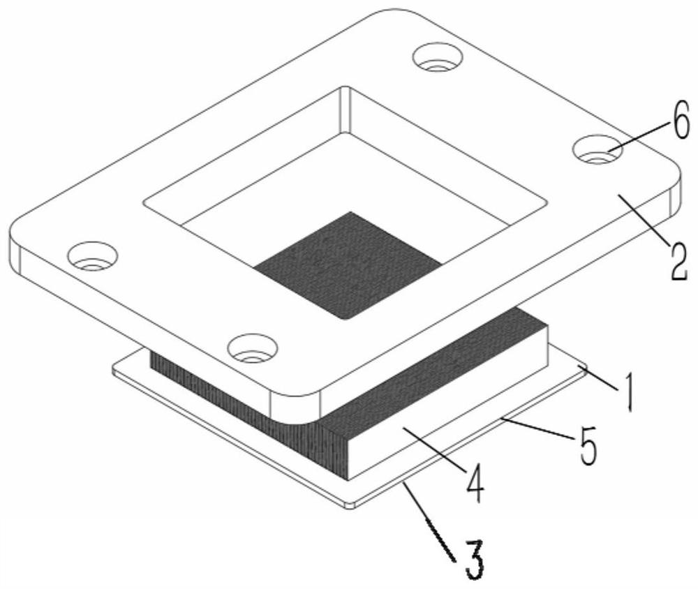
[0099] refer to figure 1 As shown, in a typical embodiment, an immersion cooling radiator includes a boiling heat exchange unit 1 and an upper assembly unit 2 thereof. Wherein, the bottom surface 3 (defined as the second surface) of the boiling heat exchange unit 1 is a smooth surface, and the top surface (defined as the first surface) is processed with a rectangular groove structure 4 . The upper end surface of the assembly unit can be processed with a number of screw holes 6 for fixing, which are used to cooperate with bolts or screws to combine the radiator with the heating element.

[0100] see again figure 2 As shown, in this embodiment, the boiling heat exchange unit 1 and the assembly unit 2 in the immersion cooling radiator are manufactured separately.

[0101] Among them, the boiling heat exchange unit 1 is a red copper plate, one side of the plate is a smooth surface, and the other side is machined with a rectangular micro-groove structure 4, and the depth and wid...

Embodiment 2

[0108] The submerged cooling radiator provided by this embodiment also has figure 2 The structure shown includes a boiling heat exchange unit 1 and its upper assembly unit 2; the boiling heat exchange unit 1 is a copper flat plate, one side of which is a smooth surface, and the other side adopts a tooth-shoveling machine to process a rectangular micro-groove structure 4, each The depth and width of the rectangular microgrooves are the same; the assembly unit is made of copper substrate, and the bottom edge is connected with the edge 5 of the side containing the microgrooves of the boiling heat exchange unit through friction welding. Fixing screw holes 6 are processed on the upper surface of the assembly unit, and the heating element is connected with the smooth surface of the boiling heat exchange unit through a film-shaped heat-conducting material (not shown in the figure).

[0109] In this embodiment, the aforementioned microgrooves have a depth of 8 mm, a width and a pitch...

Embodiment 3

[0113] The submerged cooling radiator provided by this embodiment also has figure 2 The structure shown includes a boiling heat exchange unit 1 and an assembly unit 2; the boiling heat exchange unit 1 is a copper plate, one side of which is a smooth surface, and the other side adopts a spade machine to process a rectangular groove structure 4, the depth of the rectangular groove and The widths are all the same; the assembly unit is made of red copper base material, and the bottom edge is connected to the edge 5 of the side containing the microgroove of the boiling heat exchange unit by soldering, and the welding temperature is 230°C. The upper surface of the assembly unit is processed with screw holes 6 for fixing, and the heating element and the smooth surface of the boiling heat exchange unit are connected through a film-shaped heat-conducting material (not shown in the figure).

[0114] In this embodiment, the aforementioned microgrooves have a depth of 8 mm, a width and a...


PUM


Abstract

The invention discloses an immersion cooling heat dissipation structure, a radiator, a heat dissipation system and a manufacturing method of the immersion cooling heat dissipation structure. The immersion cooling heat dissipation structure comprises a boiling heat exchange unit, and the boiling heat exchange unit comprises a first surface and a second surface which are arranged back to back; a microstructure composed of a plurality of opposite convex parts and/or a plurality of opposite concave parts is distributed on the first surface, and the first surface is at least used for making contactwith an electrically insulating immersion cooling medium; the second surface is a smooth face and used for being attached to a heating element, or the second surface and the heating element are integrally arranged. The immersion cooling heat dissipation structure provided by the invention has the advantages of higher heat exchange area, more nucleation sites, stronger capillary fluid infusion capability, excellent boiling heat exchange performance, high heat transfer coefficient and critical heat flux density, low superheat degree of a nucleation boiling starting point and great advantages ina small-space high-heat-flux heat dissipation application scene; meanwhile, the manufacturing process is relatively flexible and controllable, the cost is low, industrial large-scale application canbe achieved, and the market competitiveness is high.

Description

technical field [0001] The invention relates to a high-efficiency heat transfer structure, in particular to an immersion cooling heat dissipation structure, a radiator, a heat dissipation system and a manufacturing method thereof, belonging to the technical field of micro-nano structure design and processing. Background technique [0002] In recent years, with the development of electronic chips towards integration, miniaturization, and high power, traditional heat dissipation technologies have become more and more difficult to meet the heat dissipation needs of small spaces and high heat flow. To solve this problem, immersion cooling technology came into being. This new technology directly immerses heating elements such as electronic chips into FC-72, Novec7100 and other organic working fluid coolants, and the coolant undergoes violent nucleate boiling on the chip surface to take away heat to achieve efficient electronic cooling. Aiming at the technical problems that the s...

Claims


Application Information

Patent Timeline
Patent Type & Authority Applications(China)
IPC IPC(8): H01L23/44H01L23/427H01L21/48
CPCH01L21/4882H01L23/427H01L23/44
Inventor 高雪峰王睿陈诗翰高志强吴菲菲
Owner SUGON DATAENERGYBEIJING CO LTD
Why Eureka
Try Eureka