
Heat pipe type solid-liquid phase transition heat accumulator

A solid-liquid phase change, phase change heat storage technology, applied in heat storage equipment, heat exchanger types, indirect heat exchangers, etc., can solve the problem of slow heat storage and heat release process, insufficient reliability, and insufficient heat transfer area and other problems, to achieve the effect of rapid heat storage and heat release process, improve work reliability, and improve the distribution of holes

Inactive Publication Date: 2014-11-19
SOUTHEAST UNIV
View PDF7 Cites 27 Cited by
  • Summary
  • Abstract
  • Description
  • Claims
  • Application Information

AI Technical Summary

Problems solved by technology

In the concentric sleeve heat accumulator, since each small chamber is connected, it is difficult for each small chamber to operate independently. Once a heat exchange tube is damaged, it will have a great impact on the performance of the entire heat accumulator, making its reliability insufficient.
In a single independent phase-change material container, each small container is respectively set on the working fluid conduit. Although the above-mentioned shortcomings are overcome, due to the complicated PCM filling process, it brings a lot of inconvenience to the actual production and application.
In addition, due to the insufficient heat transfer area, the heat storage and heat release process of the traditional solid-liquid phase change accumulator is slow, and it cannot be quickly adjusted according to the change of heat supply and demand.

Method used


Image

  • Heat pipe type solid-liquid phase transition heat accumulator
  • Heat pipe type solid-liquid phase transition heat accumulator
  • Heat pipe type solid-liquid phase transition heat accumulator

Examples


Embodiment Construction

[0024] Carry out further detailed description below in conjunction with accompanying drawing:

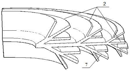
[0025] For easy observation, figure 1 A 1 / 4 perspective view of the fork-shaped heat pipe heat accumulator of the present invention is given. A heat pipe heat accumulator with a fork-like structure is composed of a box body 1, fins 2, and a phase-change heat storage material 3. The box body 1 includes two parts, the main channel 4 and the shell 5, and the cold / hot fluid 11 flows through the main channel to exchange heat with the heat accumulator. A thermal insulation material 6 is placed on the surface of the shell 5; a phase-change thermal storage material 3 is filled in the gap between the box body 1 and the fins 2. The fins 2 are arranged around the main passage 4, and multi-layer fins are arranged along the axial direction of the main passage. The fins 2 extend radially and form branch fins.

[0026] figure 2 A schematic diagram of the structure of the fork-shaped heat exc...


PUM


Abstract

The invention discloses a heat pipe type solid-liquid phase transition heat accumulator which comprises a box body, fins, liquid absorbing cores, phase transition heat accumulating materials and working media. The box body comprises a shell and a main channel formed in the shell, the two ends of the main channel are opened, the main channel is not communicated with the shell, the shell is internally provided with the fins and the phase transition heat accumulating materials, the fins are fixed to the main channel, the fins are annularly arranged about a center shaft of the main channel, and are arranged in the axial direction of the main channel in multiple layers, the ribs are of hollow structures, the liquid absorbing cores are attached to the inner walls of the hollow structures, and the spaces in the fins are filled with the working media for heat transferring between heat or cold sources and the phase transition heat accumulating materials through evaporating and condensing. According to the heat pipe type heat accumulator, the fins achieve heat exchange between the heat or cold sources and the solid and liquid phase transition heat accumulating materials through evaporating and condensing of the internal working media, and the working efficiency of the heat accumulator is improved.

Description

technical field [0001] The invention relates to a heat storage device, in particular to a solid-liquid phase change heat accumulator based on the heat pipe principle and a forked fin structure. Background technique [0002] In the energy utilization system, due to the inconsistency between energy supply and energy consumption, the energy utilization is unreasonable, which makes it difficult to effectively utilize a large amount of waste heat. In this context, phase change heat storage technology came into being. Compared with liquid-gas and solid-gas phase change accumulators, solid-liquid phase change accumulators are widely used in waste heat recovery, solar energy storage, and heating and air conditioning due to their advantages of high volume heat storage density and small temperature difference of heat storage. system. Solid-liquid phase change heat storage technology utilizes the absorption and release of energy when Phase Change Materials (PCM, Phase Change Material...

Claims


Application Information

Patent Timeline
Patent Type & Authority Applications(China)
IPC IPC(8): F28D20/02F28D15/04
CPCY02E60/14
Inventor 陈永平徐世杰邓梓龙张程宾
Owner SOUTHEAST UNIV
Learn More