
System for online monitoring faults of electric power line

A monitoring system and power line technology, applied in the field of electric power, can solve problems such as difficult power supply systems and transmission lines to operate safely and stably, reduce troubleshooting speed and efficiency, and fail to know fault information at the first time, so as to achieve good ventilation Heat dissipation performance, improved quality and service life, closed tight effect

Inactive Publication Date: 2014-01-01
ZHEJIANG BIZMAN ELECTRIC
View PDF8 Cites 33 Cited by
  • Summary
  • Abstract
  • Description
  • Claims
  • Application Information

AI Technical Summary

Problems solved by technology

This method is time-consuming and laborious, and it is difficult to ensure the safe and stable operation of the power supply system and transmission lines. Therefore, people are looking for a more effective way to solve the above problems
[0006] There are several existing fault location methods: impedance method, fault analysis method (power frequency parameter method), traveling wave method, etc. Although after decades of research and development, the accuracy of fault location devices has been greatly improved. But there is a common problem: that is, to measure the transmission line parameters and physical quantities at the time of fault, and to locate by calculation, but there will always be errors in the measurement, so the positioning results will have errors. When the above methods are used at the same time, the operator of the line in the line cannot know the fault information at the first time, and cannot implement the deployment of the line operator to the fault point, which greatly reduces the speed and efficiency of troubleshooting

Method used


Image

  • System for online monitoring faults of electric power line
  • System for online monitoring faults of electric power line
  • System for online monitoring faults of electric power line

Examples


Embodiment Construction

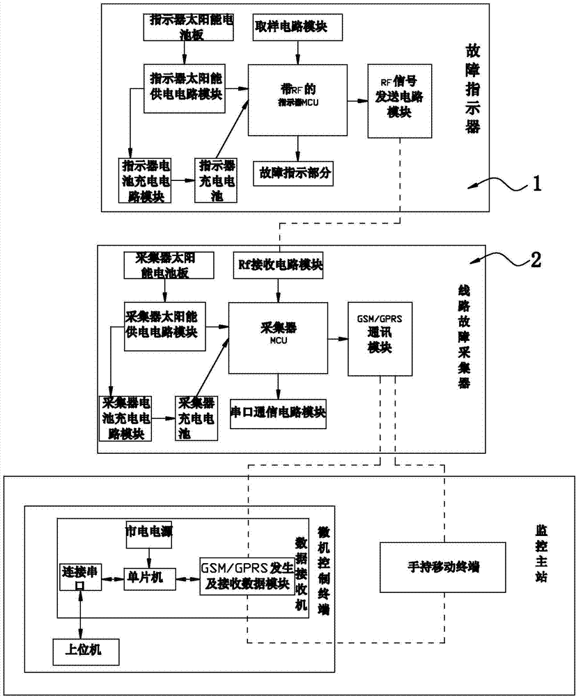
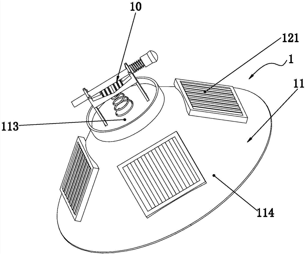
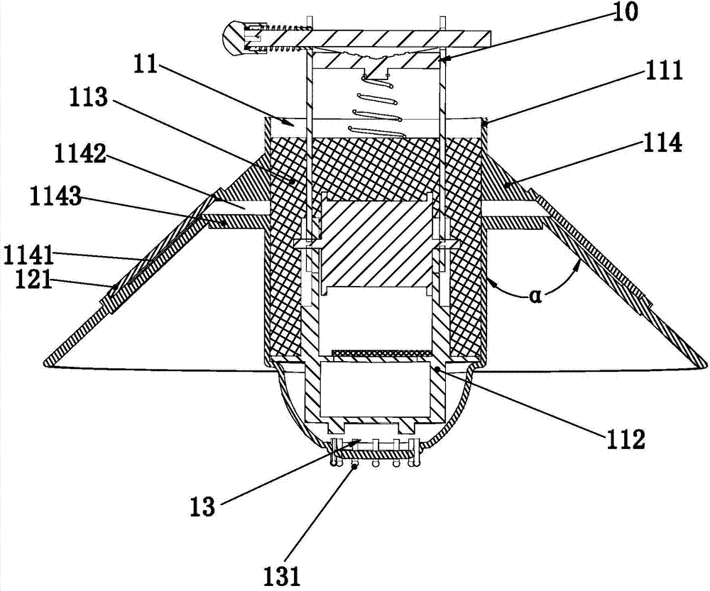
[0035] See attached figure 1 to attach Figure 5 , a power line fault online monitoring system disclosed in the present invention includes a remote terminal device and a monitoring master station; the remote terminal device includes several groups of fault indicators 1 placed on the line and several line fault data collectors 2. A group of fault indicators 1 is composed of three indicators 1 respectively placed on the three-phase line, and the one fault data collector 2 is at least connected to a group of fault indicators 1 by short-distance wireless sensor network communication; In this specific embodiment, the fault data collector 2 and the fault indicator 1 are connected through a 2.4G radio frequency network. The master monitoring station includes a hand-held mobile terminal and a microcomputer control terminal; the line fault collector 2 is connected to the hand-held mobile terminal via a mobile communication network; the line fault collector 2 is connected to the microc...


PUM


Abstract

The invention relates to a system for online monitoring faults of an electric power line. The system comprises a remote terminal device and a monitoring master station, wherein the remote terminal device comprises a fault indicator and a line fault data collector which are in communication connection by an RF (radio frequency) network, the monitoring master station comprises a handheld mobile terminal and a microprocessor control terminal, the line fault data collector communicates with the data receivers of the handheld mobile terminal and the microprocessor control terminal through a GSM / GPRS (global system for mobile / general packet radio service) communication module by a mobile communication network, and the upper computer of the microprocessor control terminal communicates with the handheld mobile terminal through a GSM / GPRS generating and receiving data module of the data receiver by the mobile communication network. According to the system, intelligent monitoring is realized; in the manners of on-site indication and remote fault alarm, the fault types and fault points are confirmed, the faults are located accurately and timely; as two terminals are adopted, the faults are alarmed timely, reasonable dispatch is realized, the fault elimination efficiency is improved, and the power distribution reliability is improved.

Description

technical field [0001] The invention relates to the technical field of electric power, in particular to an online fault monitoring system for electric power lines used for real-time monitoring of faults in field overhead lines. Background technique [0002] The transmission line is the lifeblood of the power system, and it is responsible for the transmission of electric energy. With the increasing scale of the power system and the increasing number of high-voltage, high-energy, and long-distance transmission lines, once the transmission line fails, it will have a greater impact on the safe operation of the power system, industrial and agricultural production, and people's daily life. , so it is very important to ensure the safe operation of transmission lines. [0003] The high-voltage and ultra-high-voltage transmission lines on the power grid are very long, some are hundreds of kilometers long, and some are even thousands of kilometers long. Its distribution area is wide...

Claims


Application Information

Patent Timeline
IPC IPC(8): G01R31/08
Inventor 冯存金
Owner ZHEJIANG BIZMAN ELECTRIC
Learn More