In-situ synthesis method of nano oxide catalyst coated hydrogen storage alloy composite
A technology of nano oxides and hydrogen storage alloys, which is applied in fuel cells, transportation and packaging, fuel cell additives, etc. It can solve the problems of hydrogen storage alloys being easily corroded, catalysts cannot be uniformly coated, and high-capacity batteries cannot be met. Problems, to achieve the effect of improving electrochemical cycle stability and kinetic performance, improving charge and discharge efficiency and high temperature discharge efficiency, and improving cycle stability and kinetic performance
- Summary
- Abstract
- Description
- Claims
- Application Information
AI Technical Summary
Problems solved by technology
Method used
Image

Examples
preparation example Construction
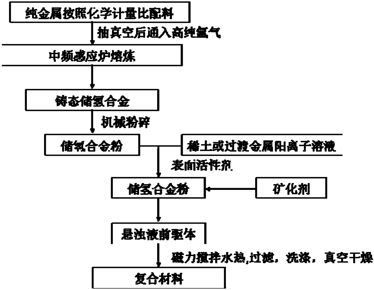
[0033] For the nano-oxide-coated hydrogen storage alloy composite material of the present invention, the present invention specifically provides a preparation method, such as figure 1 shown, including the following steps:
[0034] S101: According to the chemical composition La 1-x-y RE x Mg y Ni 3.5-a-b m 1a M2 b The batching is carried out, followed by smelting, and the cast alloy ingot is obtained and crushed to obtain hydrogen storage alloy powder. specifically:
[0035] First, according to the chemical composition La 1-x-y RE x Mg y Ni 3.5-a-b m 1a M2 b Dosing; wherein, x, y, a and b are atomic ratios, 01 and M 2 Indicates the main group and transition metal elements, including Ti, V, Mn, Fe, Co, Cu, Zn, Al, Si, etc.; magnesium and RE rare earth metals increase the amount of burning loss by mass ratio of 5% to 15% during the batching, all The purity of the metal raw material is higher than 99.7%.
[0036] Secondly, put the prepared metal raw materials in a m...
Embodiment 1
[0047] This embodiment provides a method for preparing a nano-oxide-coated hydrogen storage alloy composite material, which includes the following steps:
[0048] S101: First, metals with a purity higher than 99.7% are stoichiometrically La 0.6 PR 0.15 Mg 0.25 Ni 2.7 co 0.2 Si 0.1 Dosing; Rare earth metals and metal Mg increase the proportion of burning loss by 5% and 8% when proportioning. Secondly, after that, the intermediate frequency induction melting furnace is used for melting, and the conditions are: vacuumize to 4×10 -4 , filled with high-purity helium to 0.1MPa, and heated at 1300°C to ensure that the metal is fully melted; the molten alloy was cast into a water-cooled copper mold under a protective gas, and cooled to room temperature with the furnace to obtain an as-cast alloy ingot. Thirdly, the prepared as-cast alloy ingot is ground with a grinding wheel to remove the surface oxide layer, and then mechanically crushed into a powder with a particle size of le...
Embodiment 2
[0059] This embodiment provides a method for preparing a nano-oxide-coated hydrogen storage alloy composite material, which includes the following steps:
[0060] S101: First, metals with a purity higher than 99.7% are stoichiometrically La 0.6 PR 0.15 Mg 0.25 Ni 2.7 co 0.2 Si 0.1 Dosing; Rare earth metals and metal Mg increase the proportion of burning loss by 5% and 8% when proportioning. Secondly, after that, the intermediate frequency induction melting furnace is used for melting, and the conditions are: vacuumize to 4×10 -4, filled with high-purity helium to 0.1MPa, and heated at 1300°C to ensure that the metal is fully melted; the molten alloy was cast into a water-cooled copper mold under a protective gas, and cooled to room temperature with the furnace to obtain an as-cast alloy ingot. Thirdly, the prepared as-cast alloy ingot is ground with a grinding wheel to remove the surface oxide layer, and then mechanically crushed into a powder with a particle size of les...
PUM
 Abstract
Description
Claims
Application Information
 - Generate Ideas
- Intellectual Property
- Life Sciences
- Materials
- Tech Scout
- Unparalleled Data Quality
- Higher Quality Content
- 60% Fewer Hallucinations
Browse by: Latest US Patents, China's latest patents, Technical Efficacy Thesaurus, Application Domain, Technology Topic, Popular Technical Reports.
© 2025 PatSnap. All rights reserved.Legal|Privacy policy|Modern Slavery Act Transparency Statement|Sitemap|About US| Contact US: help@patsnap.com