
Methods and devices for thermal treatment

a technology of thermal treatment and treatment method, which is applied in the direction of osmotic delivery, diagnostic recording/measuring, therapy, etc., can solve the problems of limited commercial application of transdermal drug delivery systems, difficult transdermal delivery, and inability to meet the needs of most protein or biotech active agents, so as to reduce the barrier properties, reduce the barrier, and minimize the barrier properties

Active Publication Date: 2014-04-08
KONINK PHILIPS ELECTRONICS NV +1
View PDF17 Cites 17 Cited by
  • Summary
  • Abstract
  • Description
  • Claims
  • Application Information

AI Technical Summary

Benefits of technology

This method enhances the transdermal delivery of active agents by creating controlled micropores in the skin, allowing for efficient permeation of drugs and analyte sampling, offering a non-invasive, flexible, and effective alternative to conventional delivery methods.

Problems solved by technology

To date, commercial exploitation of transdermal drug delivery systems has been limited to only a few specific active agents, because of the practical problems to be overcome.
These problems include the solubility of the drug, the effect of the drug on the adhesive layer and delivery of the drug to the skin and through the stratum corneum and viable epidermis into the systemic circulation at a constant rate over a prolonged period.
Transdermal delivery is difficult because of skin's highly impermeable outer layer called stratum corneum.
Conventional drug delivery using pills or injection is often not suitable for most protein or biotech active agents, DNA and other nucleic acid constructs, and other therapies currently proposed and envisioned.
Despite these advantages, transdermal drug delivery is severely limited by the poor permeability of human skin; most drugs do not cross skin at therapeutic rates and only a dozen drugs have been approved by FDA for transdermal delivery since the first patch was introduced 25 years ago.

Method used


Image

  • Methods and devices for thermal treatment
  • Methods and devices for thermal treatment
  • Methods and devices for thermal treatment

Examples


example 1

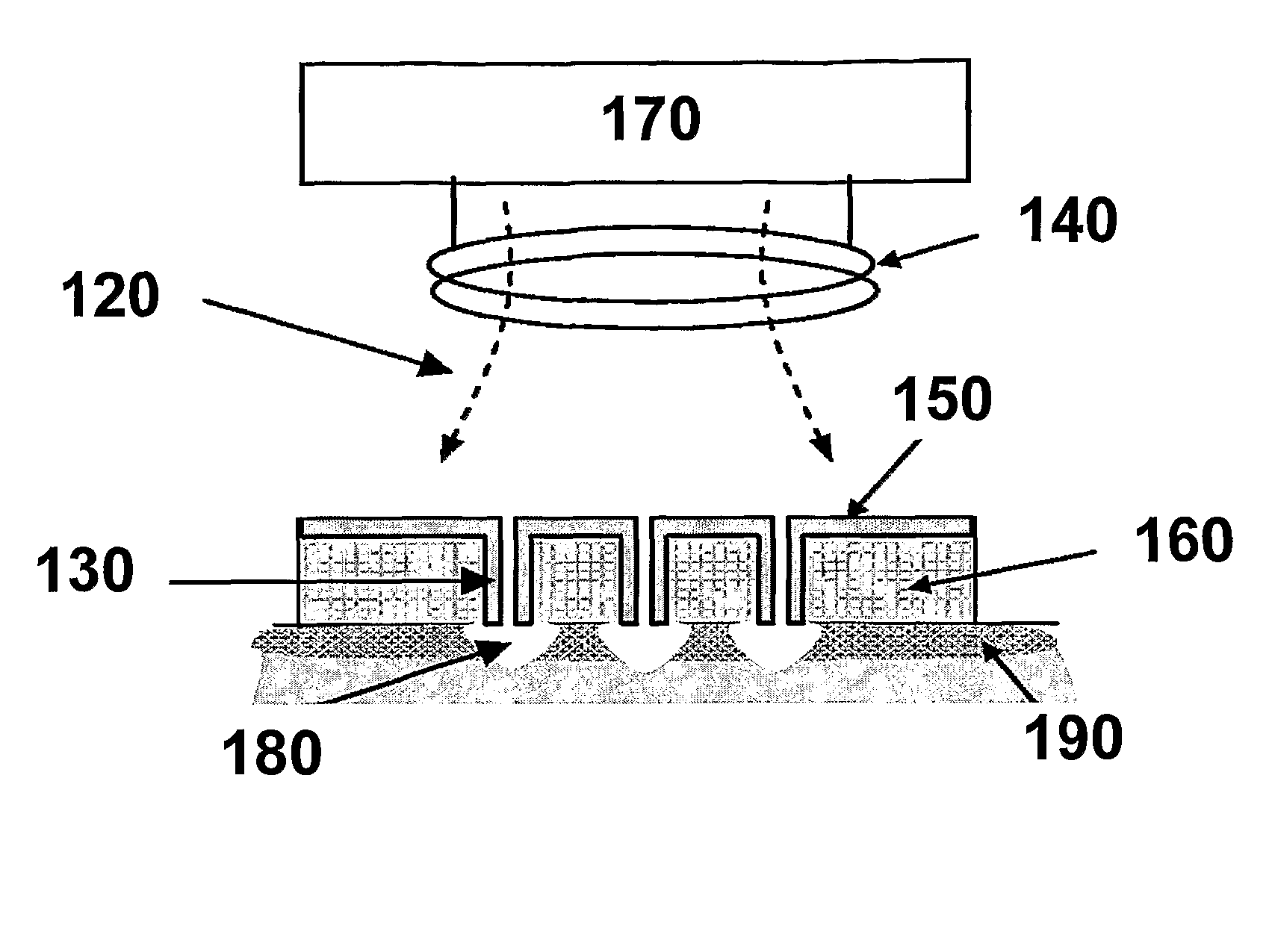
[0075]The hollow post type microheater was fabricated as follows. Photosensitive epoxy polymer SU8 (Microchem, Newton, Mass., USA) was patterned to form an array of posts on a dummy substrate (glass, 2″×3″×1 mm, Dow Corning, Midland, Mich., USA) and an electroplating seed layer of Ti / Cu was deposited on it using a DC sputterer (CVC DC sputterer, CVC, USA). Polymethylmethacrylate solution (PMMA, Microchem, Newton, Mass., USA) was applied to the posts. Reactive ion etching (RIE) was performed to expose the top portion of the posts using a reactive ion etcher (Plasma-Therm RIE, Plasma-Therm, ST. Petersburg, Fla., USA), and the exposed seed layer was removed by wet-etching (sulfuric acid (10 ml)+H2O (100 ml) and hydrofluoric acid (5 ml)+H2O (100 ml). The remaining PMMA was removed by an organic solvent (ethyl lactate) rinse. Nickel was electroplated on the seed layer, and the protruding SU8 was polished away. Polydimethylsiloxane (PDMS, Dow corning, Midland, Mich., USA) is applied evenl...

example 2

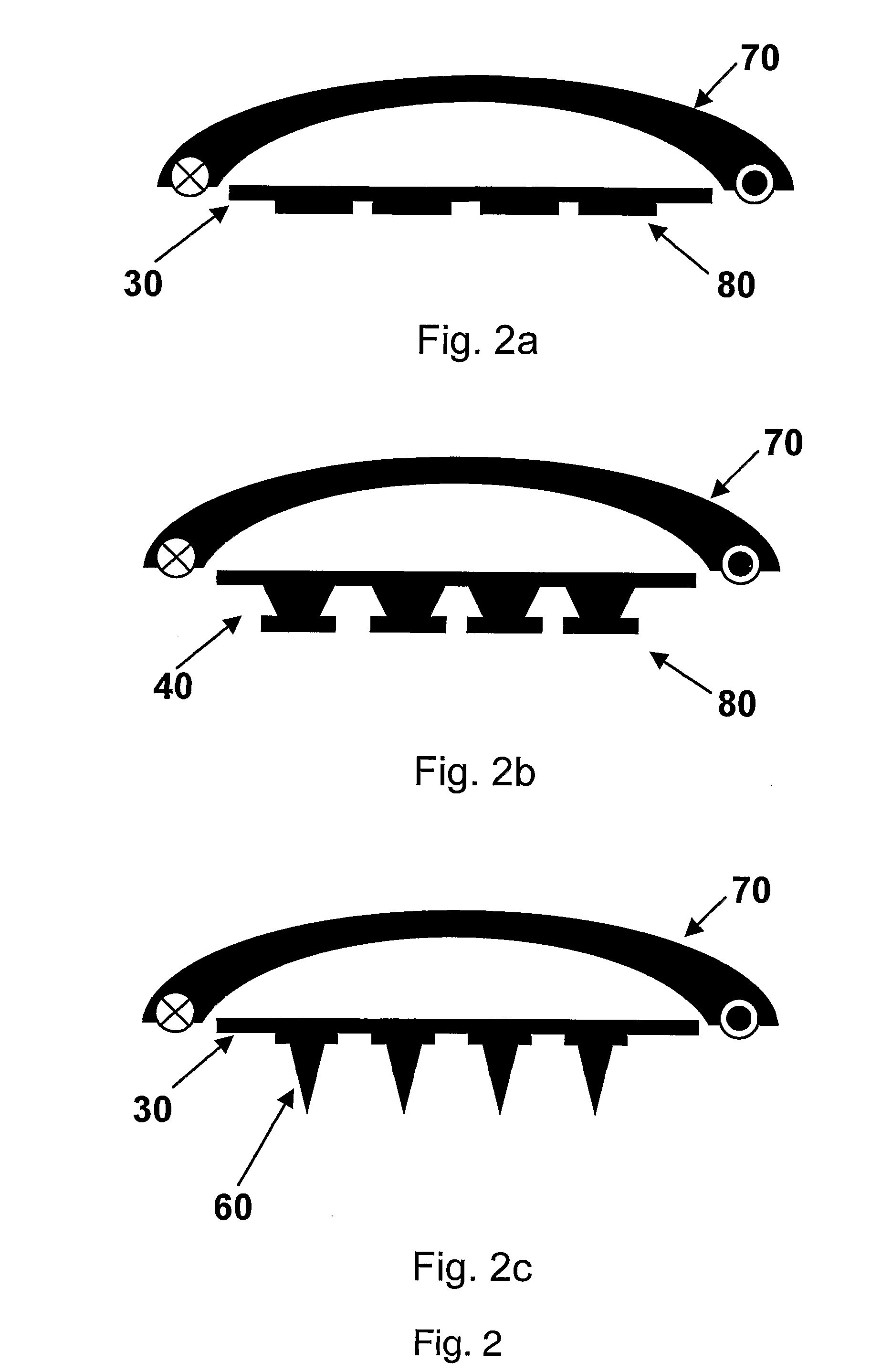
[0076]The induction heating performance of the fabricated hollow post array of EXAMPLE 1 has been characterized while applying an AC magnetic field with the excitation coil. Liquid crystal polymer (LCP) paper, which changes its color permanently when a temperature exceeds pre-set temperatures of 110, 121 or 161° C., was used as a temperature indicator for initial studies. The hollow post array was placed on top of the temperature indicator papers inside the coil, and an AC current of controlled duration (0.05 second increment) and specified frequency was applied to the coil. The resulting temperature data is shown in FIG. 9. The excitation time was recorded when each LCP paper changed color. Therefore, the x axis of graph represents the minimum time required to achieve the given temperature (the y axis). The RMS magnetic field applied to the heating element was approximately 50 auss at frequencies of 282 and 342 kHz. Since eddy current loss in the micro-heating element increases wit...

example 3

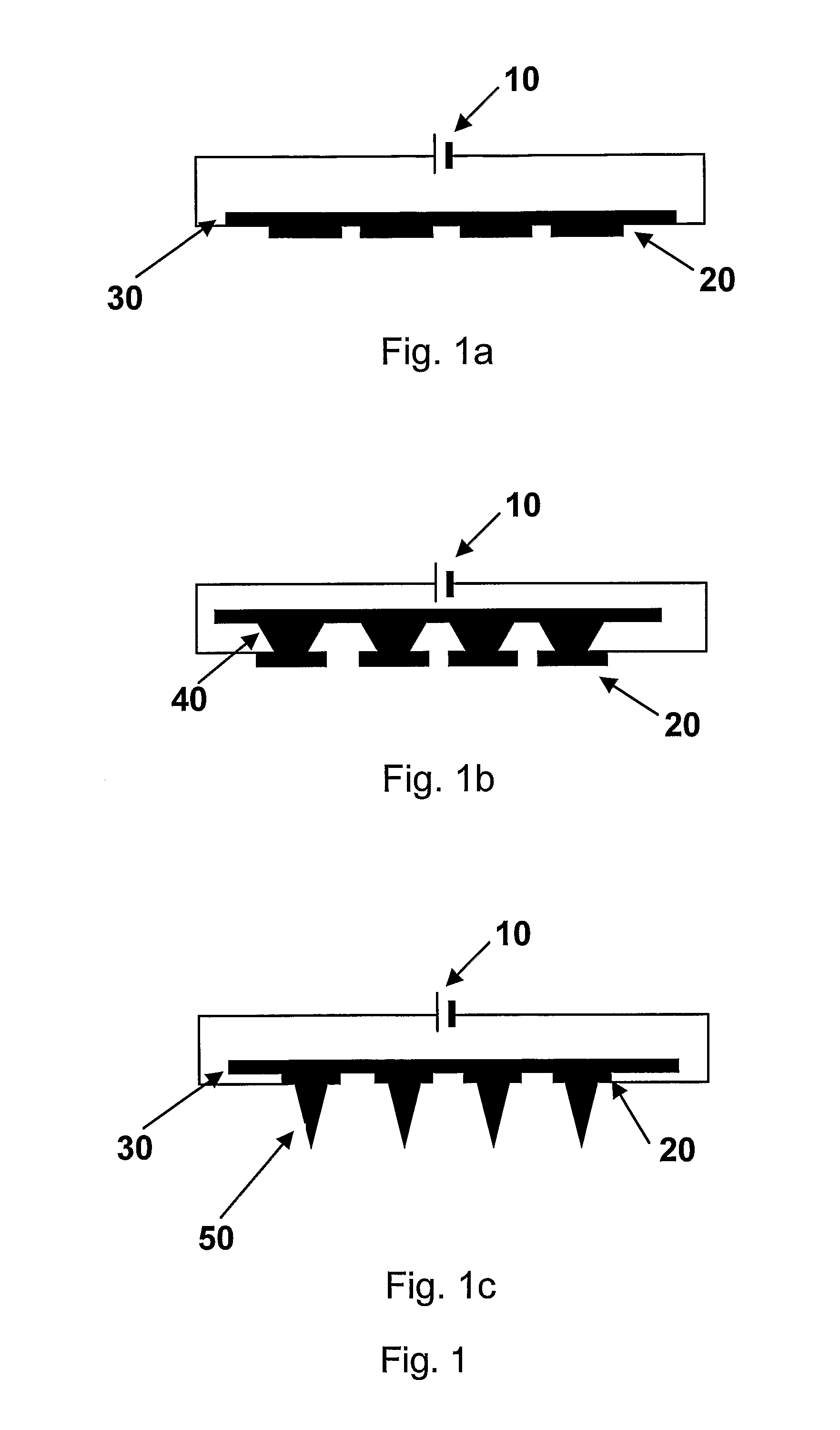
[0079]The microheaters of the present invention, one with a cone shape and one with the hollow posts, were applied to an in-vitro skin ablation experiment. FIG. 10 is a photomicrograph and FIGS. 11a and 11b is a scanning electron micrograph (SEM) of human cadaver skin (stratum corneum and epidermis) after the microheaters were applied to the skin, activated and removed. Two sites of local skin micro-ablation in the position of the conical tips and an array of donut-shaped openings in the shape of the tips of the hollow posts are shown in FIGS. 10 and 11a and 11b, respectively. The fabricated microheaters created localized micro-ablation in human skin.

[0080]To simulate an in-vivo experiment, the conical microheater was applied and energized on the skin of a hairless rat immediately after death. The skin specimen was then removed and prepared for sectioning using a cryostat microtome. As shown in FIG. 12, the skin was indented due to pressing the cone-shaped microheater against the sk...


PUM


Abstract

The present invention comprises methods and devices for thermal treatment of a barrier to increase the permeability of the barrier. One form of increasing the permeability of the barrier comprises forming micropores which may be used for administration of active agents across the barrier, or may be used for sampling or collecting fluids, or may be used for detecting, measuring or determining analytes, or may be used for monitoring of physiological or other conditions. Devices of the present invention may comprise microheaters that are activated by inductive or ohmic heating power supply components.

Description

RELATED APPLICATIONS[0001]This application claims the priority of U.S. Provisional Patent Application No. 60 / 575,717, filed May 28, 2004, which is herein incorporated in its entirety.BENEFIT CLAIMS[0002]This application is a US National Stage of International Application No. PCT / US2005 / 019035, filed 31 May 2005, which claims the benefit of U.S. Provisional Application No. 60 / 575,717, filed 28 May 2004.GOVERNMENT LICENSE RIGHTS[0003]The U.S. Government has a paid-up license in this invention and the right in limited circumstances to require the patent owner to license others on reasonable terms as provided for by the terms of Contract No. 8-ROI-EB00260-03 awarded by the National Institutes of Health, and under Contract No. F33615-02-C-1160, awarded by the U.S. Air Force.TECHNICAL FIELD[0004]The present invention relates to methods using MEMS thermal treatment devices for increasing the permeability of barriers, for example by creating openings in barriers, such as skin, for providing...

Claims


Application Information

Patent Timeline
Patent Type & Authority Patents(United States)
IPC IPC(8): A61B18/08A61N1/30
CPCA61N1/0476A61M2037/0046A61B5/14514A61B18/10A61B2018/00613A61K9/0004A61K41/0047A61N1/327A61M2037/0007A61M37/0092A61K9/7023A61N1/0492A61N1/0412A61B2018/00005A61M37/0015A61B18/082
Inventor PRAUSNITZ, MARK R.ALLEN, MARK G.PARK, JUNG-HWANYOON, YONG-KYUPARK, JIN-WOO
Owner KONINK PHILIPS ELECTRONICS NV
Learn More