Conductive member for image-forming apparatus

Inactive Publication Date: 2010-01-05
SUMITOMO RUBBER IND LTD
View PDF13 Cites 9 Cited by
  • Summary
  • Abstract
  • Description
  • Claims
  • Application Information

AI Technical Summary

Benefits of technology

[0022]It is another object of the present invention to provide a image-forming apparatus which has preferable electrical characteristics, consumes a small electrical power, and provides a preferable high-quality image for a long time.
[0158]The flame-retardant belt is formed by molding the thermoplastic elastomer containing a specified amount of the polyester thermoplastic elastomer as its main component, a specified amount of the melamine cyanurate serving as the flame-retardant additive, a specified amount of the anion-containing salt, and a specified amount of the copolymer having the polyether block. Therefore the belt is provided with excellent fire retardance without affecting its volume resistivity adversely. Further it is possible to obtain a belt which has a smooth extruded surface, does not stain the photosensitive member, and has superior driving performance and durability owing to its proper degree of elasticity. The belt has a small rise in its electrical resistance value during successive energization. Thus when the belt is used as an intermediate transfer belt of the image-forming apparatus, it is possible to reduce the range of control of the electrical resistance value which requires change of a voltage to be applied thereto. Therefore owing to the use of the belt, the image-forming apparatus provides a preferable image, and the mechanism thereof can be simplified.

Problems solved by technology

Thus it is very difficult to control the electrical resistance of the electroconductive polymer composition.
In addition, it is difficult to disperse the conductive filler uniformly in the polymer composition.
Thus if there are variations in the dispersion state of particles, it is difficult to control the electrical resistance value.
Carbon black makes the belt black, which makes it difficult to visually detect the stain of the belt.
In the case where the belt is made electroconductive by the use of the metal oxide, for example, conductive zinc white, the belt is frail if the charging amount increases owing to a low electrical resistance.
There is a problem in the dispersion state of particles of the conductive filler.
Thus it is difficult to control the electrical resistance value.
It is very difficult to adjust the electrical resistance value of the belt to 104 Ω·cm to 1012 Ω·cm.
The above-described problem of the roller and the belt causes large variations in the electrical resistance value between members of an image-forming apparatus.
Thus it is difficult to accomplish mechanical control of an image-forming process including charging, development, transfer, and fixing, which may lead to the increase of the manufacturing cost.
The use of carbon makes coloring difficult.
However, the ionic-conductive roller or the ionic-conductive belt composed of the semi-conductive polymeric elastic material disclosed in Japanese Patent Application Laid-Open No. 10-169641 is incapable of sufficiently reducing the degree of dependence on environment (temperature and humidity) in its electrical resistance value, although the rise of the electrical resistance value thereof is suppressed during successive energization by adding the quaternary ammonium salt having particular anions to the polymeric material.
Another problem of the semi-conductive polymeric elastic material is that a photosensitive member is stained in dependence on the kind of the salt, the situation in which the ionic-conductive roller or the ionic-conductive belt is used, and the contents of the semi-conductive polymeric elastic composition.
These ionic-conductive agents bleed or bloom because they are not fixed in the polymer composition.
In addition, the medium consisting of the low molecular weight compound shift to the surface of the polymer composition, thus causing stain of the photosensitive member owing to its shift and fixing of toner when the conductive member is used for a long time.
Thus the conductive member cannot be put into practical use.
Actually, these problems occur in the image-forming apparatus when it is used successively for a long time.
However, the ionic-conductive endless belt disclosed in Japanese Patent Application Laid-Open No. 2002-304064 has a problem that the volume resistivity depends greatly on environment and rises greatly during successive energization.
In this case, it is difficult to control the voltage for transfer, which makes the mechanism of the image-forming apparatus complicated and requires a large power source.
Thus the image-forming apparatus consumes a large electrical power and hence the manufacturing cost is high.
If the polymer composition of the ionic-conductive roller or the ionic-conductive belt contains a low molecular weight antistatic agent having a function of a surface-active agent, there is a fear that bleeding causes stain of the photosensitive member.
It is difficult to handle sodium perchlorate (NaClO4) in kneading with a thermoplastic elastomer.
In addition, the sodium perchlorate is expensive.
Because the conductive belt is mounted inside the image-forming apparatus at a high voltage and temperature, there is a fear that the use state of the conductive belt is restricted in dependence on the condition of environment inside the image-forming apparatus, if the belt is flammable and insufficiently flame-retardant.
When the belt contains the halogen-containing flame-retardant agent, toxic gases such as dioxin are generated when the belt is subjected to a high temperature in discarding it.

Method used


Image

  • Conductive member for image-forming apparatus
  • Conductive member for image-forming apparatus
  • Conductive member for image-forming apparatus

Examples


examples 1 through 6

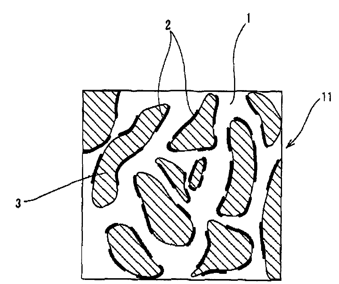
[0210]As the polymer composing the uncontinuous phase, the EO-PO-AGE copolymer was used in the examples 1 through 4 and the example 6, and the epichlorohydrin rubber was used in the example 5. The salt 1 consisting of lithium-bis (trifluoromethanesulfonyl) imide or the salt 2 consisting of lithium-tris (trifluoromethanesulfonyl)methide was distributed to the EO-PO-AGE copolymer and the epichlorohydrin rubber. The lithium-bis(trifluoromethanesulfonyl) imide and the lithium-tris (trifluoromethanesulfonyl)methide are the salt capable of dissociating into cations and anions. The low-nitrile NBR was used to form the continuous phase in the examples 1 through 6. In the examples 1 through 4, the EPDM was used to form the other uncontinuous phase (the second uncontinuous phase). Except the conductive roller of the example 2, the conductive rollers of the other examples was formed as rollers having a layer made of cellular material. The salt 2 had an electrical conductivity of 3.6 mS / cm, whe...

example 7

[0211]Epichlorohydrin rubber (50 phr), NBR, calcium carbonate, hydrotalcite-like compound, zinc oxide, and stearic acid were kneaded by an enclosed kneader preheated at 120° C. While they were being kneaded, a master batch of a thiourea type crosslinking agent (vulcanizing agent 2) prepared in advance by mixed with the epichlorohydrin rubber (10 phr), and a vulcanizing accelerator (vulcanizing accelerator 3) for the thiourea crosslinking agent were supplied to the kneader to perform dynamic crosslinking. An operator watched a chart of a kneading torque during the crosslinking operation. When the crosslinking proceeded in the neighborhood of a torque peak, the kneading operation was suspended. The mixture was cooled to 50° C. Then sulfur, a vulcanizing accelerator 1, and a vulcanizing accelerator 2 were supplied to the kneader to perform a kneading operation. As a result, a dynamically crosslinked composition was obtained. The composition was tubularly extruded as in the case of the ...

examples 8 through 11

[0212]The EO-PO-AGE copolymer was used as the polymer composing the uncontinuous phase in the examples 8 through 11. The salts 3 through 6 capable of dissociating into cations and anions were distributed to the EO-PO-AGE copolymer of the examples 8 through 11 respectively. The salt 3 was potassium-bis(trifluoromethanesulfonyl) imide. The salt 4 was hexyltrimethylammonium-bis(trifluoromethanesulfonyl) imide. The salt 5 was 1-ethyl-3-methylimidazolium-bis (trifluoromethanesulfonyl) imide (abbreviated as EMI-TFSI). The salt 6 was 1-ethyl-3-methylimidazolium-tetrafluoroborate (abbreviated as EMI-BF4).

[0213]The other specifications were similar to that of the example 2. The conductive rollers of the examples 8 through 11 were solid (not cellular).

[0214]The salt 4 was a quaternary ammonium salt of trimethyl type (three of R1 through R4 are methyl group) whose cations are shown by the chemical formula 2. The salt 5 was an imidazolium salt in which one of R5 and R6 is a methyl group and the...


PUM

PropertyMeasurementUnit
Temperatureaaaaaaaaaa

Abstract

A conductive layer of a conductive member for an image-forming apparatus is composed of a conductive polymer composition containing an ionic-conductive addition salt. The conductive polymer composition has a continuous phase and one or more uncontinuous phases including at least one first uncontinuous phase. The continuous phase and the uncontinuous phase form a sea-island structure. A salt capable of dissociating into cations and anions is unevenly distributed to the first uncontinuous phase. A polymer composing the first uncontinuous phase has a higher degree of affinity for the salt capable of dissociating into cations and anions than a polymer composing the continuous phase to prevent the salt (or the cations, the anions) from shifting out of the first uncontinuous phase or out of the polymer composition. The conductive polymer composition can contain melamine cyanurate so that it is flame-retardant.

Description

[0001]This Nonprovisional application claims priority under 35 U.S.C. § 119(a) on Patent Application No(s). 2002-344366 and 2003-038820 filed in Japan on Nov. 27, 2002 and Feb. 17, 2003, respectively, the entire contents of which are hereby incorporated by reference.BACKGROUND OF THE INVENTIONField of the Invention[0002]The present invention relates to a conductive member such as a conductive roller and a conductive belt for use in an image-forming apparatus; and a method of manufacturing the conductive member. More particularly, the present invention is intended to improve the degree of the dependence of the electrical resistance of a conductive polymer composition on environment and the change of the electrical resistance with time to thereby obtain a preferable image reliably. The conductive polymer composition is used to compose a conductive layer of a conductive member such as the conductive roller and the conductive belt for use in the image-forming apparatus such as a copying...

Claims


Application Information

Patent Timeline
IPC IPC(8): B32B27/00H01B1/20B29C48/08B29C48/34B29C70/58B29C70/88C08L71/02
CPCB29C47/0021B29C47/28B29C70/58B29C70/882C08L71/02B29C47/20B29K2995/0005Y10T428/3154B29L2029/00Y10T428/31931Y10T428/31786Y10T428/31855C08L2666/24B29C48/08B29C48/32B29C48/34H01B1/20
Inventor HATTORI, TAKAYUKIUESAKA, KENICHIOCHI, JUNTANAKA, MASAKAZUTERAKAWA, KATSUMIKI, YOGUN
Owner SUMITOMO RUBBER IND LTD
Why Eureka
Try Eureka