Eureka AIR delivers breakthrough ideas for toughest innovation challenges, trusted by R&D personnel around the world.

Electronic endoscope system

a technology of endoscopy and endoscopy, which is applied in the field of electronic endoscopy systems, can solve the problems of inability to acquire information on the oxygen saturation level of hemoglobin in blood vessels, and the inability of a single device to measure the oxygen saturation level when the depth varies, so as to facilitate the acquisition of characteristics information

Inactive Publication Date: 2011-09-29
FUJIFILM CORP
View PDF7 Cites 187 Cited by
  • Summary
  • Abstract
  • Description
  • Claims
  • Application Information

AI Technical Summary

Benefits of technology

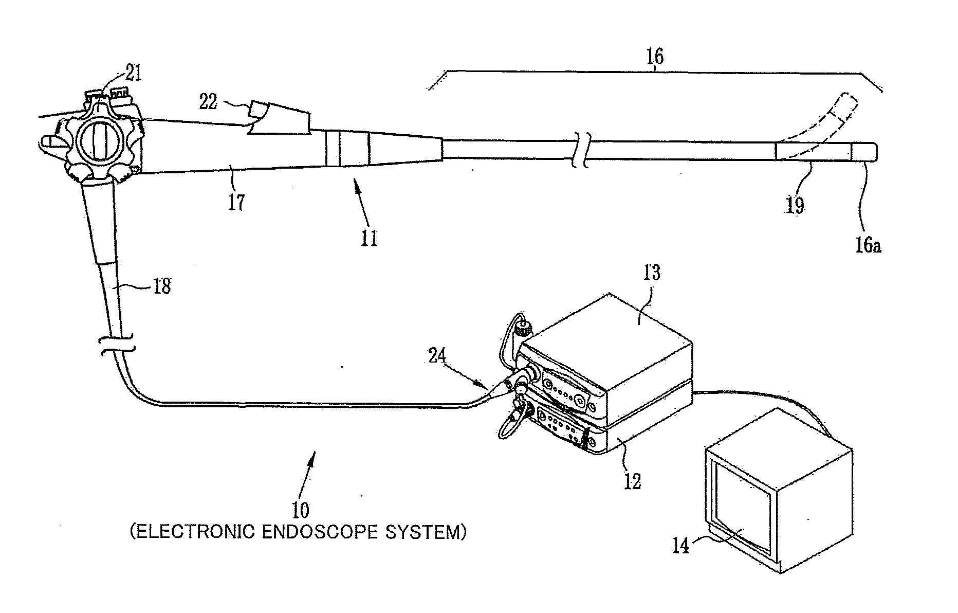
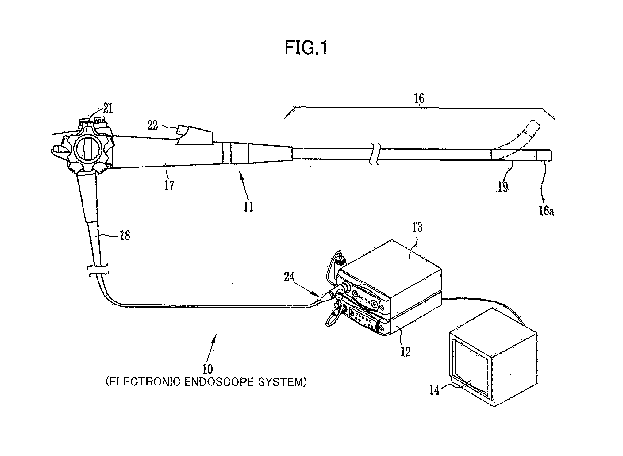
An object of the present invention is to provide an electronic endoscope system capable of simultaneous acquisition of information on blood vessel depth and oxygen saturation level and simultaneous display of images related to oxygen saturation levels of blood vessels lying in different depths.
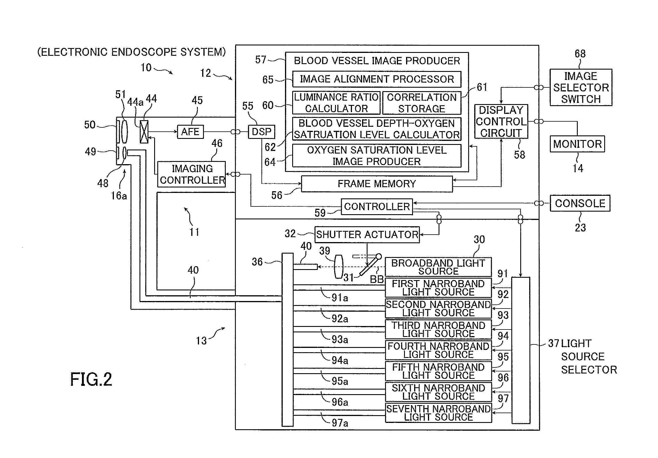
Preferably, the electronic endoscope comprises a monochromatic image sensor that converts the received light into the imaging signal through photoelectric conversion, and wherein the light source device emits narrowband light having a first central wavelength in such an emission order that the narrowband light having the first central wavelength is emitted between narrowband light having second and third central wavelengths that permit easier acquisition of characteristics information of the subject tissue than does the narrowband light having the first central wavelength.

Problems solved by technology

However, according to the method described in JP 2648494 B, the depth at which the oxygen saturation level can be measured must remain the same, making it impossible for a single device to measure the oxygen saturation level when the depth varies.
The method described in JP 3583731 A permits acquisition of configuration information for a desired depth but is unable to acquire information on the oxygen saturation level of hemoglobin in a blood vessel.

Method used


Image

  • Electronic endoscope system
  • Electronic endoscope system
  • Electronic endoscope system

Examples


Embodiment Construction

The electronic endoscope system according to the present invention will be described in detail based on preferred embodiments illustrated in the attached drawings.

The electronic endoscope system according to the present invention simultaneously obtains the oxygen saturation levels of hemoglobin in blood vessels in different depths by switching between illumination wavelengths for imaging depending on the depth of a blood vessel to be imaged as measured from the surface of the subject tissue and simultaneously displays a plurality of images of oxygen saturation levels at different depths.

An embodiment described below uses seven kinds of narrowband light having different central wavelengths of 405, 445, 473, 532, 560, 650, and 800 nm as a light source for acquiring a distribution of oxygen saturation levels of blood vessels in different depths. In view of general characteristics of light that the reaching depth as measured from the surface of a subject tissue attained by light emitted...


PUM


Abstract

An electronic endoscope system includes a light source device for sequentially emitting light having different wavelength bands, an electronic endoscope for receiving reflected light of light sequentially illuminating a subject tissue containing a blood vessel in a body cavity and sequentially outputting an imaging signal corresponding to the wavelength band of the received light, an aligner for aligning images corresponding to imaging signals obtained using light having different wavelength bands outputted from the electronic endoscope, an image producer for producing an oxygen saturation level image representing the distribution of the oxygen saturation level in the blood vessel in a given depth from the imaging signals of the images aligned by the aligner, and an image display for displaying the oxygen saturation level image produced by the image producer.

Description

BACKGROUND OF THE INVENTIONThe present invention relates to an electronic endoscope system for acquiring information on a blood vessel from an image acquired by an electronic endoscope and displaying the acquired information.In recent years, a number of diagnoses and treatments using electronic endoscopes have been made in the field of medicine. A typical electronic endoscope is equipped with an elongated insertion section that is inserted into a subject's body cavity. The insertion section has therein incorporated an imager such as a CCD at the tip thereof. The electronic endoscope is connected to a light source device, which emits light from the tip of the insertion section to illuminate the inside of a body cavity. With the inside of the body cavity illuminated by light, the subject tissue inside the body cavity is imaged by an imager provided at the tip of the insertion section. Images acquired by imaging undergoes various kinds of processing by a processor connected to the elec...

Claims


Application Information

Patent Timeline
Patent Type & Authority Applications(United States)
IPC IPC(8): A61B1/04
CPCA61B1/00156A61B1/0638A61B5/14551A61B1/0646A61B5/489A61B1/063A61B5/1459A61B1/000094A61B1/0655
Inventor CHUN, MINKYUNG
Owner FUJIFILM CORP
Why Eureka
Eureka Blog
Learn More